R8 injects the bias current only for the up side output transistor Q3. There is no idle current for Q2.
Sorry, this isn't possible, unless you want the bias current run through the speaker load.
Best regards!
The original QUAD 405 had zero bias on the output, but in the 405-2 they included a single diode between the output devices bases. That still kept them in class B, but it just gave them a minimal bias (0.3V per B-E) to make turn-on just a bit smoother.
I think that is a very good idea. You are still in class B but make turn-on just that much smoother for less crossover distortion.
Jan
I think that is a very good idea. You are still in class B but make turn-on just that much smoother for less crossover distortion.
Jan
class b
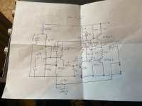
Its a long time since i uploaded any information I hopes this works
The cabinets were made for me by a Mr Peter Steel of Hope street Hanley
Transformers were wound for me by a local guy in Longton and were rated at 300 va
Output devices were BD 184 supplied by Farnel
Drivers were bd237/bd238
Note the stabilized supply This was done as the off load voltage was to igh for the output devices At this time high voltage devices were not really available to the likes of me
Any way this was self conceived no access to things like Amcron or Phase linear
I just thought of a low impedance driver that would carry the load through the time the output devices were not on
Trev
Attachments

Your schematics show germanium AD142 power devices, not BD's.
Anyway, this obiously is a guitar amplifer, where ultra low distortion figures don't matter that much, if anything at all. Even »clean« sounds benefit from the enhancement by some THD.
Best regards!
Anyway, this obiously is a guitar amplifer, where ultra low distortion figures don't matter that much, if anything at all. Even »clean« sounds benefit from the enhancement by some THD.
Best regards!
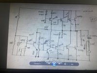
Sorry an error on my part
I have thousands of schematics and i have sent you the wrong one I will attach the coorect one now
I have thousands of schematics and i have sent you the wrong one I will attach the coorect one now
class b
please view the attached of the actual circuit
Not at all a guitar amplifier as stated earlier these worked for a large no of years as a music pa system in fact 10 amplifiers were used these did deliver 150 watts RMS into a 4 ohm load
they sounded nice at a low level Having said that the drivers were critical and the unit would not work with tip 31/32 c
Trevor
Attachments
please view the attached of the actual circuit
Not at all a guitar amplifier as stated earlier these worked for a large no of years as a music pa system in fact 10 amplifiers were used these did deliver 150 watts RMS into a 4 ohm load
they sounded nice at a low level Having said that the drivers were critical and the unit would not work with tip 31/32 c
Trevor
It is a neat design even today.
Hard to believe when I made these I read about the 2n3773 I tried to obtain some but no luck
It would be another 2 years before they could be obtained from Farnell /RS
I was well aware of total DC coupling etc
The output capacitor was a political choice I wanted no comeback re burnt out voice coils if the amplifier went DC
very much a hybrid construction front end on vero drives and outputs point to point wired
The units when installed did not physically move for 30 odd years
Decent heat sinking and a large PSU were the main secrets
I would take another 10 years before i ever looked at an Amcron and at least 25 years before i saw a phase linear
I was lucky enough to get into audio just as valves were being phased out and transistors were making their mark
I later went on to use line output transistors due to the high VCE but hats another story
Trev
Did you really? I remember that the power dissipation ratings of sweep transistors was rather low, about in the 10 - 20 watts range. So you'd need multiple pairs even for a small AF amplifier
Best regards!
Best regards!
You are correct maybe 5 pairs but not impossible
I received the bu208 by accident fitted tham and was delighted by the results
The end result was not dissimilar to Amcron / Phase linear
But with my own front end and capacitor output
I am not a great believer in Dc coupling as i do not have dc coupled ears
Trev
I received the bu208 by accident fitted tham and was delighted by the results
The end result was not dissimilar to Amcron / Phase linear
But with my own front end and capacitor output
I am not a great believer in Dc coupling as i do not have dc coupled ears
Trev
There's a historical example of no bias current in the output stage. It was the Dynaco Stereo 120.
I got one of those. Bought it for historical reasons and it was cheap.
It sounds...terrible.
I figured that is because of discontinuities at the 0 crossing and while integrated over time distortion may be quite low during the zero crossing it is 100%.
But then who knows?
Not at all a guitar amplifier as stated earlier these worked for a large no of years as a music pa system in fact 10 amplifiers were used these did deliver 150 watts RMS into a 4 ohm load
they sounded nice at a low level Having said that the drivers were critical and the unit would not work with tip 31/32 c
The TIP31/32 are absolutely TERRIBLE as drivers for any amp where you expect low crossover distortion. What you really want are *any* of the standard Japanese “driver” transistors similar to the old C4793/A1837. The available types change almost every 6 months these days but the general idea is the same.
TIP31/2 are “ok” as the 2nd stage of an EF3/QC, but only if they’ve got something fast out in front driving *them*. But a better driver is still better. As EF2 drivers - useless. They are not even particularly rugged. Just DON’T DO IT.
Probably one of the reasons for the infamous "transistor sound" of the seventies.It sounds...terrible.
I figured that is because of discontinuities at the 0 crossing and while integrated over time distortion may be quite low during the zero crossing it is 100%.
But then who knows?
As I said above, I didn't like the sound of my "real class B" amplifier, yet it is much less brutal than just a lack of bias resulting in class B-C operation.
My solution is an almost pure and pristine class B, text-book like without any heavy FB to polish-off discontinuities, but the steering transistor doesn't operate instantly, and this causes a tiny burst of HF crap at the zero crossings.
Objectively, it doesn't impact the THD figure at all, and the harmonics produced are well beyond the hearing range: in fact, any class D amp produces much larger artefacts before the output filter.
Without GNFB, there is a large content of even harmonics, mainly H2, because of the asymetrical conditions, and this should make the sound more pleasant -except it doesn't, and I hate even-order distortion, even more than odd order-. I might be an exception though
Um, no, jxdking is correct.
Did you look at jxdking's circuit? R8 is a passive pull-down to the negative rail that causes the upper OP to remain slightly on in order to maintain ~zero offset. In effect, the crossover is moved away from zero volts. So below about 100mV (32V/1k*4) the amp is class-A.
I have considered doing this myself but eventually decided that it was not the best idea. Just using the PNP driver in class-A,AB a bit harder is a better idea. Switching the CE OP of the CFP does not cause as much THD as switching a CC OP because it is relatively Hi-Z and the PNP driver reacts with local feedback.
Years ago when I was repairing big power amps, I would under-bias them assuming it would help prevent repeat failure. Cross-coupling is also very useful at preventing failures because it drastically reduces shoot-through current when driven fast. But there is no good way to cross-couple a quasi amp. Crown DC-300 amps used 0.5V Vbe (~class-B) on the OPs and ~10 Ohm base resistors to turn them off as fast as possible.
Sorry, this isn't possible, unless you want the bias current run through the speaker load.
Best regards!
Did you look at jxdking's circuit? R8 is a passive pull-down to the negative rail that causes the upper OP to remain slightly on in order to maintain ~zero offset. In effect, the crossover is moved away from zero volts. So below about 100mV (32V/1k*4) the amp is class-A.
I have considered doing this myself but eventually decided that it was not the best idea. Just using the PNP driver in class-A,AB a bit harder is a better idea. Switching the CE OP of the CFP does not cause as much THD as switching a CC OP because it is relatively Hi-Z and the PNP driver reacts with local feedback.
Years ago when I was repairing big power amps, I would under-bias them assuming it would help prevent repeat failure. Cross-coupling is also very useful at preventing failures because it drastically reduces shoot-through current when driven fast. But there is no good way to cross-couple a quasi amp. Crown DC-300 amps used 0.5V Vbe (~class-B) on the OPs and ~10 Ohm base resistors to turn them off as fast as possible.
I did this back in the 1972 for me it id not wok I then met it again With D self i think he called it class X it just moved xover distortion from 0 to another point
Anyway its all not important a Quad proved with the 405 in the mid 70,s
There were problems with he 405 re current limiting etc but the amp worked
Trev
Anyway its all not important a Quad proved with the 405 in the mid 70,s
There were problems with he 405 re current limiting etc but the amp worked
Trev
Did you look at jxdking's circuit? R8 is a passive pull-down to the negative rail that causes the upper OP to remain slightly on in order to maintain ~zero offset.
I beg your pardon, you're right. I must have been overlooking that R8.
Best regards!
Crown DC-300 amps used 0.5V Vbe (~class-B) on the OPs and ~10 Ohm base resistors to turn them off as fast as possible.
That low Rbe forces about 50 mA of bias in the driver transistor too. At low signal levels it really runs off the driver transistors (remove the outputs and see for yourself). At 50 mA of bias, crossover distortion is low. The extremely high NFB in these amps reduces that “10 ohm output impedance” to low values. Crossover distortion is initially very low, rises again somewhat as the outputs actually begin to get used, then drops at the usual rate. Use that same output stage without all that NFB and it’s *awful*.
When I tested my class B amplifier i drove a 1 ohm resistor to a few watts and this enabled me to examine the transfer function of the drivers and output devices this indicated a rise in gain as and when the output transistors turned on !
Of course driving normal 4-8 ohm loads this slope was not as pronounced
Distortion measurements were also low below 1 percent at any level up to clipping
Square wave response at 1kz and 10 Khz was also quite good using q 120 pf capacitor around the Vas
stability was also very good
In fact I made a pair of cabinets with 2 by 12 bass units with the heat sinks in the base reflex slot
Cooling on these was excellent
Sound levels were much higher than expected
Eagle tweeters for Hf
Goodmans Midax for the mids and Richard allan drivers for the bass
Oh happy days
Aren't the old Phase Linear 400/700s and Crown DC300s considered "Class B"? Zero current through the output transistors at idle. Idle current is in the drivers.
Craig
Craig
I would consider that to be the case they are class AB +B
if you look at Crowns original specs they specify at low level then high level but do not mention the transition level
Their is a better way the Renardson circuit Its an Ab circuit with local feedback loops that
prevents Gm doubling all in all the work of a true genius simple but I wish I thought of it first
Trev
- Home
- Amplifiers
- Solid State
- 0 Bias Class B, Possible?