It's about thermal tracking and thermal run away. The idle current drifts as the temperature changes so zero idle current is less likely to thermal run-away. Thermal tracking is not easy and no help if you don't have enough heat sink. The dissipation of class-B and AB amps and current dumping is almost the same when driving any amount or power. For better efficiency you need class-H or class-D. Audio amps should have thermal shut-down but few do.
Class C
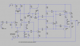
Here is the one I just came up with 0 bias current output stage, highlighted portion.
About the THD figure, I think Multisim is joking with me, 0.001% THD @10KHz.
I am happy if THD can get 0.5% below in reality.

Here is the one I just came up with 0 bias current output stage, highlighted portion.
About the THD figure, I think Multisim is joking with me, 0.001% THD @10KHz.
I am happy if THD can get 0.5% below in reality.
0.001% is probably not realistic, but at the max power, the THD is certainly very low.
THD @1W could be a different story though
THD @1W could be a different story though
I've successfully simulated a class b+g circuit with 3mA bias current per output pair.
0.1W/4R THD20k 0.00015%
1W/4R THD20k 0.00012%
10W/4R THD20k 0.00012%
100W/4R THD20k 0.00014%
0.1W/4R THD20k 0.00015%
1W/4R THD20k 0.00012%
10W/4R THD20k 0.00012%
100W/4R THD20k 0.00014%
I doubt that this amplifier is a low distortion one. Instead, it tries to compensate the crossover by massive NFB. I don't read Kirillic letters, nor do I understand the Russian language, but I seen to recognize in the paper's title that emphasis is thermal stability, achieved by the Sziklai pairs.Something like this?
This appears interesting. I'll have to search for this article. Sadly enough I've been a subscriber to FUNKSCHAU in those days, but have discarded all magazines a long time ago.№3 Klass AB + C and Current dumping. Original in magazine Funkschau 1977, Heft 25, z.130-134 .
Best regards!
#25 Zapf J., Schvenn R. Ein Okonomishes, vollgeschutztes Hi-Fi Verstarkerkonzept
fon 20 W bis 200 W. — Funkschau, 1977, Heft 25, z: 130 — 134
fon 20 W bis 200 W. — Funkschau, 1977, Heft 25, z: 130 — 134
This doesn't look like zero output stage bias. There's a bias current through VT1 and VT2, setting up a non-zero Vbe in the output devices.
Jan
Not everyone agrees on what class B means: zero bias current or just enough bias current to let the two sides take over from each other gracefully? Douglas Self uses the latter definition, which is also the historically correct definition as far as I know. Zero bias current is then class C, because it results in dead zones and hence in conduction angles below 180 degrees.
Anyway, that's just semantics.
This is correct. Have a close look at tube datasheets. Any operating point that is named class B reads some certain idle plate current.
Anyway, the hardcore class B definition means a conducting angle of exactly 180 degrees per device. Class A is 360 degrees, and anything in between is class AB. Less than 180 deg is class C.
In historic tube datasheets class AB frequently denominates self bias in PP amplifiers, though.
Best regarads!
Based on the definition, class B amplifier should have 0 bias current.
Well no, class B says only that each device conducts 180 degrees of the cycle, it doesn't say what happens at the crossover (which is theoretically 0 degrees!).
If output devices were perfect class B would have 0 bias current. But they are not perfect and thus you choose the optimum, or close to optimum bias point usually.
The larger the signal swing to closer output devices look to be perfect (in that the crossover region is a smaller proportion of the waveform) - but with huge signal swings the quiescent dissipation is more or less irrelevant.
Basically zero bias with real devices isn't optimum, you don't go there if you can avoid it. Its certainly possible, but not desirable - for one thing its hard to guarantee stability at the zero point, nor avoid bias drift.
The solution I proposed is almost perfect class B (save a small constant current in the upper transistor), adaptative (no adjustment or thermal compensation required), and doesn't rely on huge feedback to work:
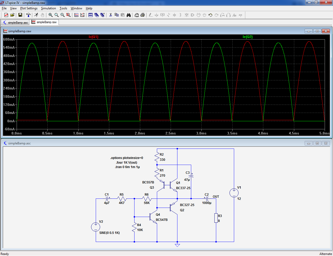
To eliminate residual imperfections, some diodes can be added.
Here is the same with bells & whistles/
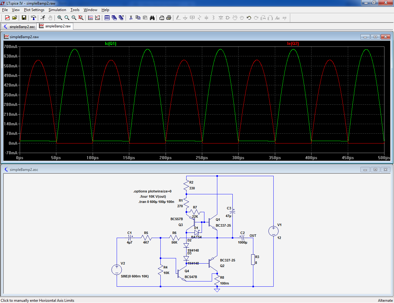
To eliminate residual imperfections, some diodes can be added.
Here is the same with bells & whistles/
Attachments
The solution I proposed is almost perfect class B (save a small constant current in the upper transistor), adaptative (no adjustment or thermal compensation required), and doesn't rely on huge feedback to work:
Here is my simulation with your trick. It totally tricked the Multisim simulation. The distortion is not measurable. (Worst case, 4 Ohm load, 1V peak to peak, @10KHz)
BTW, do you hear any artifacts/distortion based on your design with real components? I may not be able to build a prototype to verify the simulation.

***Edited***
There was error in the simulation above. I injected some idle current somehow. The THD is measurable. My bad.
Here is the revised circuitry.

Last edited:
zero bias
I think I posted this before. This is almost a blameless amp but the output is tweaked.
The bias is not enough for drivers and OP but it's the faster drivers that operate class-B,C and not the slower OPs. This means the switching is fast and less audible. Simulation saz the 1k THD is 0.001288%.
You may also notice that he VAS drives the center of the VBE and not the top/bottom of the VBE in order to improve the output swing.
Attachments
Low impedance drivers are a possible answer rather like the Phase linear or Amcron
I made for a local heavy rock disco in the early 70,s 10 off such amplifiers they worked hard for nearly thirty years without any failure
This disco or call it a rock venue was the Highwayman at Threapwood in Staffordshire here in the uk
If you define class B as no standing current in the output transistors these amplifiers filled the bill
I have since recovered one of these amplifiers after seeing it in a music shop
I went in and asked if it was for sale the shop said no!
As it was a piece of rock history I explained i designed and made these as a 19 year old
I am now 69
After hearing my story the shop owner gave me the amp no charge
By the way the shop owner is a Mr Ogden drummer of the heavy rock band Demon
I can post the circuits and show you pictures any one interested
Trev
TBH, I didn't like the sound very much. I normally rely more on the distortion-meter result than on my hears, but I found the sound rather unpleasant.BTW, do you hear any artifacts/distortion based on your design with real components? I may not be able to build a prototype to verify the simulation.
Maybe it has to do with the very small, but very harsh residues: they don't register on the THD figure, but they may impact the subjective sound quality.
A good ABX testing would be required to lift all doubts
I think that the topology is not practically usable with multiple OP devices, like darlingtons or CFP's: the steering transistor has a base current dependent on the VAS quiescent current.View attachment 972522
***Edited***
There was error in the simulation above. I injected some idle current somehow. The THD is measurable. My bad.
Here is the revised circuitry.
View attachment 972524
When there is just one transistor output layer, this results in a pseudo-quiescent current ~=to the VAS current.
When you add another layer, with a beta of ~50 for example, this results in a pseudo-Iq of hundreds of mA, if not more.
A bit hot for my taste.
You can manipulate the current, with BE resistors for example, but it is not very reliable.
If you manage to have it working effectively with doubles (or even triples), good for you.
I didn't succeed, but I would be glad to see someone managing it
I didn't succeed, but I would be glad to see someone managing it
I just watched couple Youtube videos of the demos of dynaco st-120. Based on the manual, it has zero idle current on the output transistors. In those videos, it sounds all right.
I may do some quick test with one of my class B amp on hand. It has trim pots for bias current. I could adjust the bias current all the way down. Hope it can down to zero. Then, I will report back the result. I just want to get the "proof of concept" first.
You can manipulate the current, with BE resistors for example, but it is not very reliable.
This reminds me of the old Edwin amplifier design by Elektor. The drivers did the whole thing until the voltage drop over the outputs' BE resistors exceeds the knee voltage.
Best regards!
I have an old Sansui G-4700 receiver that was given to me free because it was "blowed-up". I replaced the blown outputs and added a heat sink with 4x 2N3773. The old output REs (2/4) became the RBs for the 2N3773s and I used about 2.2 Ohms. So the original outputs go to about 0.65/2.2=~300mA before the new 2N3773s kick in. It sounded fine so I never adjusted the bias up to class AB. It was not exactly audiophile in the first place, but just fine for listening to FM radio. The tone controls are in the power amp feedback: arrg! It has since been shorted by a bad speaker connection without any failures. BGW took a similar philosophy in their old amps with massive output silicon that could handle the full power supply in a fault condition. The price of silicon (~$14) is not bad compared to the value of my time.
I adjusted the bias current to zero on my class B amp. It is a "Blameless" style typology amp. It sounds fine, without any artifacts. I admit I don't have "golden ear". There is an unexpected benefit to run bias at zero. It totally eliminated 120Hz hum of my amp. 😛 The less current, the less ripple on the power rails.
Based on simulation, for a "Blameless" style amp with zero bias, the THD @10KHz, +-1V peak, you will get -35dB THD (around 1.8%). Thus, @1KHz, you will get -55dB THD (around 0.18%). If you volume up, the crossover distortion will get less proportion, +-1V peak signal is kind of the worst case. I use 4 Ohm load in my simulation.
I did study the schematic of dynaco st-120. Its output stage behaves much better than normal 2EF output stage at zero bias point. If you swap out 2EF output stage from "Blameless" style amp with dynaco st-120 output stage, you can easily get -50dB THD (0.3%) at 10KHz.
Here is my observation.
1. To run zero bias, you kind of need local feedback to speed up the "switch" during "dead zone". dynaco st-120 uses quasi complementary output stage. The down half is known as CFP, it creates tight local feedback, it speeds up the "switch".
2. Normally, you can just keep one of up/down sides output transistor at zero bias, and leave the other side biased. It helps your THD, meanwhile it maintains the same thermal stability. Use a resistor or current source pull down/up the speaker output to achieve the desired bias. The side remains zero bias will be the side that uses CFP. Its local feedback loop helps the switching distortion. Thus, you can run the other side with EF configuration, because that side is properly biased, you don't need to use CFP.
Based on those principles mentioned above, here is my new design.
R8 injects the bias current only for the up side output transistor Q3. There is no idle current for Q2.
Last edited:
- Home
- Amplifiers
- Solid State
- 0 Bias Class B, Possible?