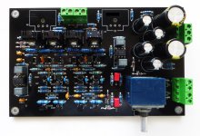
hi pavel, first of all congratulations for your work. A fet and bjt preamplifier always has its charm on me. If I can ask you a question, if you haven't already been asked: do you plan to complete DISPRE2 adding some filter and tone control stages, a riaa stage, using alway transistors and jfet? congratulation again, un saluto to everyone Ros
Thank you for your post. Never say never, but at the moment I do not plan such extension. This small lot re-production was done for the reason that time after time I am asked if I have those boards.hi pavel, …. do you plan to complete DISPRE2 adding some filter and tone control stages, a riaa stage, using alway transistors and jfet? congratulation again, un saluto to everyone Ros
LSK170C: Idss = 16.8m, 18.3m, 18.7m, 18.7m, 19.1m at 12V.
LSJ74C: Idss = 11.1m, 13.6m, 14.1m, 15.3m, 17.8m at 12V.
I have built and tested one new module with those Linear Systems LSK/LSJ parts. R8 has to be changed to 220R, everything else remains the same.


Below is the result of THD vs. output voltage at 1kHz and 10kHz, 1kohm load, measuring BW =45kHz. To me, it is fully acceptable. The usual level when used as a preamp would be <= 2V.
It can drive load down to 10 ohm. I will show further results later.
THD+N vs. output voltage at 1kHz (BW20kHz) and at 10kHz (BW45kHz) with those LSK170C/LSJ74C stock parts:


Load 1 kohm.
Load 1 kohm.
THD+N vs. output power into 47 ohm load. Please note how the preamplifier keeps low distortion, so it can be used with headphones without problems.

Hi Pavel, any subjective differences between the original and LSK parts in the overall presentation of music?
No. However, matched pairs (octets) are still the best choice to get best distortion parameters, which is important rather technically. Unmatched stock parts as I have used may need more initial settings (R8, R9 choice, as described in the manual).
Output noise voltage measured is 6.66uV ref 20kHz bandwidth, which is on pair with the Toshiba devices.
Output noise voltage measured is 6.66uV ref 20kHz bandwidth, which is on pair with the Toshiba devices.
I have tested load down to 10 ohm. It still keeps THD below 0.001%/2V. This is with standard output resistor R26=10R. Total 20R. This way, max. output is 4Vrms/10R load, i.e. 400mA output current. The output resistor R26 may be further reduced down to 1ohm. This would reduce possible FR modulation by headphone complex impedance, however, I am not sure what would happen in case of unwanted short circuit behind the 1ohm resistor.
This is distortion spectrum into 50 ohm load, at 7V (1W approx.),
 below clipping turn point. Harmonics are decreasing with their order.
Last edited:
This is the RightMark report. Measured at -2dBFS, FS = 10V, load 1 kohm. FR deviation is completely on behalf of DAC/ADC chain, the preamp FR is straight with -0.5dB/100kHz.

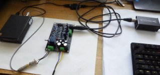
I would like to demonstrate that it is not easy to measure distortion of Dispre 2-JFET at lower output voltages, that are typical if used as a link stage preamp. My signal source is Topping D10s DAC (with USB-ISO adapter to cut the signal ground loop) and ADC is E1DACosmos. To make a comparison with DAC/ADC loop distortion, D2JFET (which has overall gain 14dB, 5x) is set by its volume pot to Gain 1. Input range of E1DA is chosen 2.7V - not to go into clipping and to keep low self noise.
THD(1kHz) vs. output voltage comparison of loopback and loop with D2JFET is shown in the image below:

Seemingly paradoxically, D2JFET has lower THD, up to 400mV, than the loopback. This is for the reason that the output of the DAC (or D2JFET) is loaded with very low input impedance of E1DA Cosmos, which is only about 700 ohm (SE) for the 2.7V input range. But, D2JFET has 10k input impedance, thus lighter load for the DAC and distortion is then slightly lower with the preamp than without it, and it also has much more powerful output stage than is the LME49720 in the D10s. 400mV is a sweet spot for D2JFET, with distortion below -120dB. Then it slowly rises. We are in absolutely inaudible levels, though.
For THD+N, situation is better for the loopback, because D2JFET has 14dB gain and output noise of about 6uV (flat 20kHz BW), and D10s has output noise below 2uV.
THD(1kHz) vs. output voltage comparison of loopback and loop with D2JFET is shown in the image below:
Seemingly paradoxically, D2JFET has lower THD, up to 400mV, than the loopback. This is for the reason that the output of the DAC (or D2JFET) is loaded with very low input impedance of E1DA Cosmos, which is only about 700 ohm (SE) for the 2.7V input range. But, D2JFET has 10k input impedance, thus lighter load for the DAC and distortion is then slightly lower with the preamp than without it, and it also has much more powerful output stage than is the LME49720 in the D10s. 400mV is a sweet spot for D2JFET, with distortion below -120dB. Then it slowly rises. We are in absolutely inaudible levels, though.
For THD+N, situation is better for the loopback, because D2JFET has 14dB gain and output noise of about 6uV (flat 20kHz BW), and D10s has output noise below 2uV.
Forgot I had the part for this one in the workshop. thanks PMA for making another run and reminding me to finish this one.
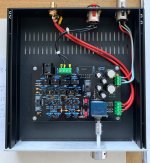
Almost complete but I want to run a few measurements by you before I get to far.
-- Inputs are shorted and volume pot at zero -- no load on output
Power V+/V- is 15V/-15V
R6 - 589mv
R11 - 591mv
R106 - 567mv
R111 - 573mv
Voltage divided by 2.7ohm shown in ( )
R24 - 85.1mv (31.518mA)
R25 - 84.7mv (31.370mA)
R124 - 79.8mv (29.556mA)
R125 - 80.9mv (29.963mA)
All parts are standard as shown on your BOM
Let me know if I am ready to roll.
I will be using as a preamp but also with 93db (16ohm) headphones.

Guiness
Almost complete but I want to run a few measurements by you before I get to far.
-- Inputs are shorted and volume pot at zero -- no load on output
Power V+/V- is 15V/-15V
R6 - 589mv
R11 - 591mv
R106 - 567mv
R111 - 573mv
Voltage divided by 2.7ohm shown in ( )
R24 - 85.1mv (31.518mA)
R25 - 84.7mv (31.370mA)
R124 - 79.8mv (29.556mA)
R125 - 80.9mv (29.963mA)
All parts are standard as shown on your BOM
Let me know if I am ready to roll.
I will be using as a preamp but also with 93db (16ohm) headphones.
Guiness
Nicely built!
The values look good. It would be good if you could also measure voltages across R5, R105, R10 and R110.
I am now using R18, R118 = 6k8 and get lower output stage idle current of 16.7 mA, output transistors are colder and parameters still hold, as shown in the latest measurements. Bur it is up to you.
As mentioned in post #177, I do not have auto-ranging measuring system and my ability to measure whole range of output voltages is thus limited. I made an attempt to put measurements with two ADC range settings (2.7V and 10V) together and here it goes. Still I would need an output divider for the DAC to eliminate its noise contribution. @BW20kHz flat.


- Home
- Source & Line
- Analog Line Level
- Preamplifier Dispre 2 - JFET

