
Happy to share with anyone who cares to build it, was quite a job, this is Rev 11. Al revision was bult tested and updated. 🤣

Attachments
Last edited:
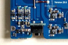
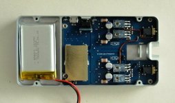
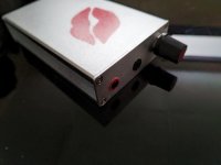
125x65mm, 160g.
JFET input, current conveyor gain stage (no global negative feedback), Class A BJT follower output.
All Toshiba active devices. Built-in passive modified Danyuk crossfeed.
Li battery powers an AD SMPS to generate +/-9.3V.
LT3045/3094 local regulators per channel +/-7.9V.
Built-in USB charger.
Patrick
.
Attachments
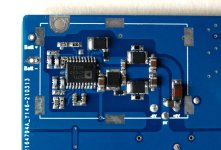
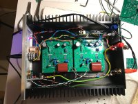
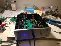
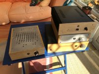
Balanced input composite amplifier based on the article "High Precision Composite OP Amps" by John D. Yewen, Electronics & Wireless World, Feb 1987 and Application Bulletin AB-051, Burr-Brown Corporation, Mar 1993. [1/2 OPA1612 and 3 OPA1688 per channel output]

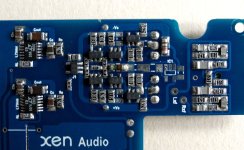
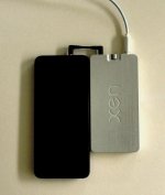
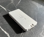
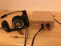
This one I've made for my father in law (who has poor hearing and uses headphones to watch news on TV). It can be used with his IPad as well.
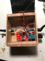
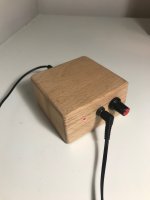
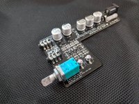
I wanted to keep it as small as possible. My first thought was a CMoy but then I realised that the world has moved on.
This is MAX4410 from Ali. It is not half bad in fact.
I wanted to keep it as small as possible. My first thought was a CMoy but then I realised that the world has moved on.
This is MAX4410 from Ali. It is not half bad in fact.
Attachments
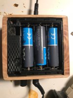
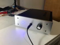


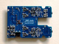
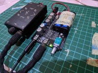
This portable amp is based on the Formula3HP by @lineup
It is powered by two 3.7V batteries in series. The sound is very clean and warm, making it comfortable for long listening sessions.
It is powered by two 3.7V batteries in series. The sound is very clean and warm, making it comfortable for long listening sessions.
Attachments
- Home
- Amplifiers
- Headphone Systems
- Headphone Amp Photo Gallery