I never tested resilience of my amp against lack of GND
I would start testing without OS parts, you have procedure explained back in thread .........
of course, try first with poking through pcb, testing each active with simple diode test, searching for shorts
I would start testing without OS parts, you have procedure explained back in thread .........
of course, try first with poking through pcb, testing each active with simple diode test, searching for shorts
I did diode test to the active pats and I want to verify my results before taking any actions. All the parts are on the pcb without removing them yet. Some parts show forward voltages ok 0,5-06V all pins but changing testing direction and polarity then they also show some short voltages. Please someone tell me that jfets are ok. 🥹 Maybe someone can verify these results in their XA252 amp?
Jfets 2sk2145 - Source and drain - 0,001V diode test (using J1 and J3 pinouts 1 and 3) It starts reading from 0,5V and after a couple of seconds it goes to 0,001V. 🥲
DN2540 - Source and Drain - 0,06V
V1 and V2 LM385-1V2 - 0,024V
Q5 - BC640 - pin 2 and 3 - 0,05V
Q8 - BC639 - pin 2 and 3 - 0,05V
OK1, OK2 - PC817 - pin 1 and 2 - 0,024V
T3 - BC546 - pin 2 and 3 - 0,06V
T8 - BC546 - pin 2 and 3 - 0,08V
do you have one channel functional?
if yes, compare
usual practice is - if diode test in situ is showing that part is ok, then ok (most likely)
if diode test is showing suspicious part, don think; remove it and test out of pcb
optos are almost certainly ok; they are protected with LM chips
if yes, compare
usual practice is - if diode test in situ is showing that part is ok, then ok (most likely)
if diode test is showing suspicious part, don think; remove it and test out of pcb
optos are almost certainly ok; they are protected with LM chips
it's enough to test JFets with diode/resistance test
if there is no short and D-S showing few dozens Ohms, they're OK
if there is no short and D-S showing few dozens Ohms, they're OK
What measurement points are used when checking for 'short'? I get the ohms part between D-S, same place for short testing?
Thanks, maybe I can torture boards less!
Russellc
Thanks, maybe I can torture boards less!
Russellc
without voltage present, D-S of JFet is presenting itself as simple resistor
so, if you have dozen-2-3 of Ohms, Jfet is most likely OK
if there is short - you either made a mess with soldering job, or JFet is Dodo
all that, counting that surrounding parts aren't messing too much with testing
so, if you have dozen-2-3 of Ohms, Jfet is most likely OK
if there is short - you either made a mess with soldering job, or JFet is Dodo
all that, counting that surrounding parts aren't messing too much with testing

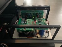
It has taken a long time to sort out some fans for heat control but my XA252 is finally singing and keeping temp at 20 deg above ambient (46deg C). Still only the test rig but sounding excellent as expected. Thanks Zen for the cajillion options for us Greedy Boyz

Anybody there who did a comparison between balanced and unbalanced input signal for this amplifier?
Is there a difference soundwise, if yes, what do you prefer most?
Possibly I'm bothering to much about the sugar, but I need to order some XLR inputs (not quite cheap) when willing to go balanced.
Monoblocks will be far enough completed next week, to put them in the main system.
Is there a difference soundwise, if yes, what do you prefer most?
Possibly I'm bothering to much about the sugar, but I need to order some XLR inputs (not quite cheap) when willing to go balanced.
Monoblocks will be far enough completed next week, to put them in the main system.
Attachments

bother with balanced only if you have proper balanced source*** and then proper balanced preamp
***inherently balanced construction, not just SE with patched in inverter stage to get negative phase
anyhow - in the end - try whatever you can think of, and use what your ears/brain prefer most
as direct reply to question regarding XA252 - I'm not finding any significant difference between two input arrangements
I have a Blowtorch clone preamp, meaning inherently balanced concstruction : https://www.diyaudio.com/community/...d-state-pics-here.96192/page-368#post-7159684
As this will be my first balanced connection in my system, I have went to quite some online infor regarding balanced connections. Including SE to balanced.
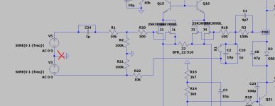
I was surprised when reading the Rane paper (Ranenote 110), ground signal from source is NOT required to connect to input GND at amplifier?? When verifying in LTspice, it seemed to work.
Can anybody confirm this really is the case, I don't want to find out the hard way. (See red cross below, can I break this connection)
As this will be my first balanced connection in my system, I have went to quite some online infor regarding balanced connections. Including SE to balanced.
I was surprised when reading the Rane paper (Ranenote 110), ground signal from source is NOT required to connect to input GND at amplifier?? When verifying in LTspice, it seemed to work.
Can anybody confirm this really is the case, I don't want to find out the hard way. (See red cross below, can I break this connection)
Attachments
in practice (speaking of your black boxes), you have a choice - connecting Pin1 either to case or to signal GND on stage pcb
audio GND is always connected to case in some way
Pin1 to case is sort of standard Pro arrangement, where Pin1 to pcb GND is more commercial gear arrangement
Practically - none is superior and right one is where there is no hum present
now, regarding cables, there is no dilemma - corresponding pins on two cable ends must be connected
there are also cables having 3 wires and then screen, where screen is exclusively connected to connector shells
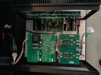
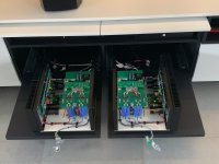
Zen Mod, congratulations with this amplifier design! The XA252’s are replacing my previous diy amp’s.
Sound is marvelous, been listening last two days as good as continuos to these amps.
Rails are 38,5V and biased at 1,2A.
PSU ripple is about 30mV for output stage, front end is equiped with cap multiplier.
When listening in High Bias mode (push button), bias is at 1,8A. But to be honest, soundwise, no difference.
Next step is getting all eclosure panels CNC milled out of HPL plate.
Attachments

Thanks Russel,
And yes, boards are selfmade: https://www.diyaudio.com/community/...elfish-xa252-set.373443/page-121#post-7803907
End this week, remaining material for completion of internal wiring and material for balanced connection to preamp will be delivered.
Material for front, side and rear panel is Egger U999 ST76. I'm out and need to order a complete plate of 4100x650mm 🙁.
Hi Ya'all ...
Been away for some time and wondered where the Mighty ZM was up to with the BBB-(Big-Bada-Boom)-252
A hell of a catch-up read, and I have much sympathy for a number who have fried R24 (and friends).
I also did this, but after I had been running the amp for some time in stable working order - so "reasonably confident" nothing installed AAF (***-about-face).
Mine occurred on the test bench when I disconnected the signal-in from a wave-generator, whilst looking at square-wave behavior.
(Yes - we all have brain-farts from time-to-time)
I assumed this must have been some stray earth-loop related/floating voltage event, however, this never really made sense and the timing may have been totally coincidental.
(Remember - "assumption" is the mother of all F-ups - and temporal association is not always causation!)
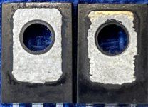
I ended-up building a whole new set of boards using the LS series JFets from DIY-Audio, as I had several sets on hand. In the rebuild process, I noticed the supplied Q1/Q2 variants were a little "shaggy" around the mounting holes. See image below - left is a local BD139 and right is the kit supplied device.
Now, I have absolutely no idea if this may have contributed to any of these failures! However, for my rebuild I wanted to absolutely exclude this from the equation, which is why I bought the all plastic case onsemi BD139/140 pairs. No insulating mica, just thermal paste and a decent sized heat-sink. One less possibility to consider!
Have now been using the XA252 for 18+ months (a lot) and remain very happy and grateful for all of ZM's work / help.
So ... ZM ... the BBB ???

Been away for some time and wondered where the Mighty ZM was up to with the BBB-(Big-Bada-Boom)-252
A hell of a catch-up read, and I have much sympathy for a number who have fried R24 (and friends).
I also did this, but after I had been running the amp for some time in stable working order - so "reasonably confident" nothing installed AAF (***-about-face).
Mine occurred on the test bench when I disconnected the signal-in from a wave-generator, whilst looking at square-wave behavior.
(Yes - we all have brain-farts from time-to-time)
I assumed this must have been some stray earth-loop related/floating voltage event, however, this never really made sense and the timing may have been totally coincidental.
(Remember - "assumption" is the mother of all F-ups - and temporal association is not always causation!)
I ended-up building a whole new set of boards using the LS series JFets from DIY-Audio, as I had several sets on hand. In the rebuild process, I noticed the supplied Q1/Q2 variants were a little "shaggy" around the mounting holes. See image below - left is a local BD139 and right is the kit supplied device.
Now, I have absolutely no idea if this may have contributed to any of these failures! However, for my rebuild I wanted to absolutely exclude this from the equation, which is why I bought the all plastic case onsemi BD139/140 pairs. No insulating mica, just thermal paste and a decent sized heat-sink. One less possibility to consider!
Have now been using the XA252 for 18+ months (a lot) and remain very happy and grateful for all of ZM's work / help.
So ... ZM ... the BBB ???
Attachments
Last edited:
I have some questions just to get to know better Babelfish XA252 amp.
ZM mentioned that this amp is tuned for 2nd harmonic negative phase.
What section in the schematic is doing that and can we adjust it to normal or 2nd harmonic positive phase? Switching speakers cables makes the lower frequencies sound weird.
Does the straight MOS schematic version also have the 2nd negative phase? What parts to pull off from SET verison to try straight MOS versions if I have populated SET version and I wanna try both versions? What would be easiest method for that? 🙄
I also like to know about this LT3092 CCS part. For simplicity you have chosen the LT3092 or some other reason? How does it affect the sound? 🤔
I am using SET schematic with FQA36P15 and FQA46N15 mosfets and PSU +-24V rails with total 80mF caps.
- Home
- Amplifiers
- Pass Labs
- Babelfish XA252 / Babelfish XA252 SIT / Babelfish XA252 SET