A month ago I was contacted by Brandon at the DIYAUDIO forum. He had seen my post on Krell Amplifier repairs and asked if I am able to help repair his Mark Levinson No 20.6. One of the monoblocks was experiencing a fault and and kept tripping and shutting down the amplifier.
I said sure. Little did I know that I was embarking on the most challenging task in my last fifty plus years experience in tinkering with amplifiers.
It is going to be a long story and I will start updating this post moving forward.

I said sure. Little did I know that I was embarking on the most challenging task in my last fifty plus years experience in tinkering with amplifiers.
It is going to be a long story and I will start updating this post moving forward.
Attachments
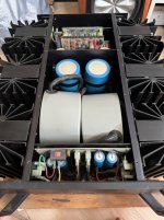

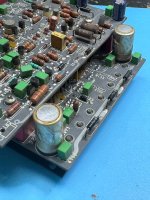
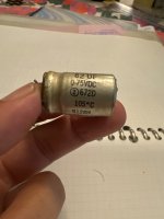
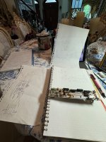
The AP-5 double decked boards had two electrolytic capacitors that certainly showed some visible damage. Look bloated.
I thought maybe I am in luck. This may be an easy fix. Replace the capacitors and all done.
Wish life is that simple. Haha
I thought maybe I am in luck. This may be an easy fix. Replace the capacitors and all done.
Wish life is that simple. Haha
Attachments

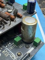

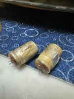
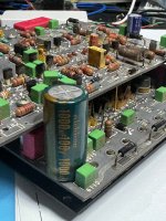
The bad capacitors were 82uF 75V and date code appears to be 1991. There is a crack on the capacitor body which appeared to have exploded open. I had some Nichicon 1,000uF 100V on hand. Seems like an overkill. I believe it doesn’t hurt.
Attachments
Put back the boards and power up. Unfortunately it tripped again. 😱
Now how does one go about repairing an amplifier that would not power up. Can’t even check any voltages.
Easiest is by elimination.
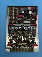
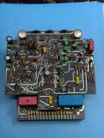
Since the AP-5 had two capacitors replaced but amp still did not work, I decided to pull out this board. Of course taking a calculated risk that removing this board does not create catastrophic damages in other part of the amp.
AP-5 removed. Still tripped.
Removed RP-3, no tripping. That’s good at least there is progress.
Now how does one go about repairing an amplifier that would not power up. Can’t even check any voltages.
Easiest is by elimination.
Since the AP-5 had two capacitors replaced but amp still did not work, I decided to pull out this board. Of course taking a calculated risk that removing this board does not create catastrophic damages in other part of the amp.
AP-5 removed. Still tripped.
Removed RP-3, no tripping. That’s good at least there is progress.
Had no idea what is the function of this board. Tried my luck trying to search for information from the internet.
Managed to find some schematics from a partial service manual.
RP-3 is apparently a regulator and protection board. Guessed it revision 3.
At least that explains why there is no trip as the protection board is plucked out.
Experienced people may comment that it was quite dumb to do that without understanding the boards function before pulling them out. For example If there was a short circuit and that’s why it tripped. By pulling out the protection card there is no protection and may have caused serious damage if there was not protection.
Sorry I did miss describing some steps before I pulled out the daughter cards. I was indeed careful as this is a high current amplifier looking at the hefty transformers.
From experience, most high power high current class A power amp tend to have failure at the output transistors as these are the ones most stressed.
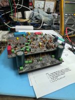
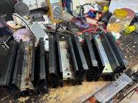
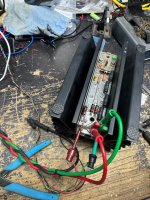
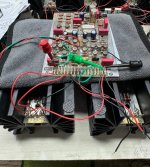
I started dismantling the heatsink modules which contained the output transistors.
Was expecting that the output modules may just be similar construction with power transistors with emitter and base resistors.
Was surprised that there were three different pairs of heatsink modules. Separate by negative side and positive side. Following labels seen on the PCB. NRP PRP NDP PDP NBP PDP. N being negative side and P positive. This information was derived actually later after studying the schematics.
Didn’t know the function at this point.
Did a quick ohmmeter test on the power transistors and non appeared on one shorted. Any which one that is blown open can’t be checked in circuit since transistors are in parallel. At least there was no shorts.
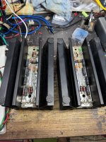
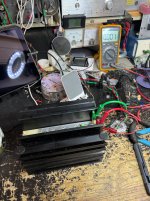
I attempted to test each module independently on the test bench to check if they were functioning.
Was expecting that the output modules may just be similar construction with power transistors with emitter and base resistors.
Was surprised that there were three different pairs of heatsink modules. Separate by negative side and positive side. Following labels seen on the PCB. NRP PRP NDP PDP NBP PDP. N being negative side and P positive. This information was derived actually later after studying the schematics.
Didn’t know the function at this point.
Did a quick ohmmeter test on the power transistors and non appeared on one shorted. Any which one that is blown open can’t be checked in circuit since transistors are in parallel. At least there was no shorts.
I attempted to test each module independently on the test bench to check if they were functioning.
Attachments
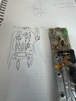
My initial schematic search was unsuccessful so I had to do a bit of circuit tracing.
Two of the modules have less components and quite easy to figure out the circuit. I was able to bias up the module on a bench power supply with current limit control. Applying power across collectors and emitter resistors and biasing a small voltage at the base I was able to test four of the modules to be functioning in this manner. By slowly increasing the base voltage the module was also slowly drawing more current.
Two of the modules have less components and quite easy to figure out the circuit. I was able to bias up the module on a bench power supply with current limit control. Applying power across collectors and emitter resistors and biasing a small voltage at the base I was able to test four of the modules to be functioning in this manner. By slowly increasing the base voltage the module was also slowly drawing more current.
Attachments
The last two modules labeled NRP and PRP were more complicated with several more components. So it obvious that using the earlier method to test wouldn’t work.
Later I figured out this was the voltage regulator module. At the same time I was surprised that Mark Levison had already started using regulated power supply for their power amplifier in the early days.
Stay tuned. It’s getting late now. Will continue posting tomorrow.
Later I figured out this was the voltage regulator module. At the same time I was surprised that Mark Levison had already started using regulated power supply for their power amplifier in the early days.
Stay tuned. It’s getting late now. Will continue posting tomorrow.
Attachments
Glad you are enjoying this. It took me
More than a month to finally nailed down the problem and fixed it.
Very satisfying indeed.
One conclusion, this ML amp is definitely meant for factory repair or by somebody that had worked in ML factory doing this or someone who been trained specifically to repair this.
As my story unfold you will understand why I came to this conclusion
After studying the traced out NRP and PRP module circuit it appeared that they needed to be biased up properly to test them.
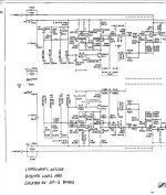
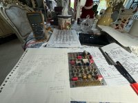
I continued to search the internet for schematics and service manual and fortunately found some useful materials.
Managed to find a partial service manual but it was very difficult to decipher the various connections among the modules.
However I was able to determine that the RP-3 PCB board was the Regulator and Protection board as it was appropriately labeled.
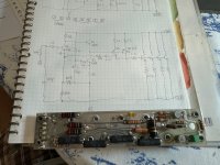
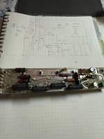
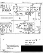
Here are two pages of the schematic for the RP-3. The part of the circuit inside by the dashed line is the PRP and NRP heatsink modules.
With this knowledge I could test out the protection and voltage regulator part of the amplifier system.
With RP-3, NRP and PRP in the system while removing AP-5, NBP PBP NDP PDP from the chassis I attempted to test the regulator and protection function independently.
Unfortunately it still tripped the amplifier at power on.
Haha. What a bummer!
What’s next. How to test without being able to power up the board and modules ?
Attachments
An idea was to test the RP-3 with the associated modules on the bench.
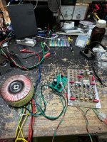
Based on another circuit in the service manual the raw unregulated supply should be around +/- 84V unloaded based on the secondary winding of 60V from the power transformer.
I built a simple +/- 85V power supply
I decided to test the RP-3 board first without connecting the NRP and PRP modules.
With the schematic on hand I could figure out that by adding a simple emitter follower at the output of the RP-3 board I should be able to test the voltage regulator function.
With that I was able to confirm that the RP-3 voltage regulator function is working.
Attachments
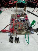
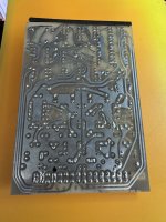
What I described seemed easy but not really that simple. The RP-3 and the heatsink modules were in fact connected via a big motherboard that occupied the entire bottom of the amplifier. With RP-3 and AP-5 inserted from the top and all the heatsink modules connected at the sides.
I had to figure out how the heatsink modules are connected through the motherboard to the RP-3 board first before I can wire them up.
Took me a while to figure that out even with the schematic. Without that it would have been a nightmare to trace the connection through the motherboard traces.
I had to figure out how the heatsink modules are connected through the motherboard to the RP-3 board first before I can wire them up.
Took me a while to figure that out even with the schematic. Without that it would have been a nightmare to trace the connection through the motherboard traces.
- Home
- Amplifiers
- Solid State
- Mark Levinson No. 20.6 Repair