The small initial diameter allows us to use a slow-expanding profile(*), without increasing the HF beaming. In fact, at the orignal exit diameter, the new profile has a wider opening angle than the original one. It gives the wavefront a longer time and distance to curve itself without much diffraction.
(*) Whatever it is - I actually have no idea how to call it, as it just emerged from optimization. But I wouldn't be surprised if it was close to exponential.
(*) Whatever it is - I actually have no idea how to call it, as it just emerged from optimization. But I wouldn't be surprised if it was close to exponential.
Makes sense. Just curious, are your typical extenders (i.e. the T520-36-EXT-1) conical or exponential? I built a throat-extension into the script but it's currently conical.
Conical is inferior, as it can't connect smoothly to a horn profile with non-zero initial curvature. For a new adapter, I always perform a new optimization of the whole system and all the adapters are the results of this process. The curves don't have names (apart from the fact that they are Bezier cubics), they are just optimal continuations of the horn (which is fixed). It's actually pretty sophisticated 🙂
Last edited:
Ok, makes sense. As far as I can tell, a Bezier cubics curve must approach something like a NURBS curve (non-uniform rational B-Spline) which is the base curvature inherent in Rhino (although I understand they are slightly different).
If I might ask a hypothetical - let's say you're developing a throat adapter for a B+C driver with a conical exit angle of 6 degrees, and your throat adapter is some 6" long for sake of this hypothetical. Given the curvature of the throat adapter, your exit angle at the end of the throat is going to be greater than 6 degrees by some nominal amount - how do you make sure that angle is tangent with the beginning of your horn? I.e. under those parameters, the initial angle of the horn curvature must always be in excess of the throat angle; thus it seems to me that in a design process it should follow that the design should start with the actual throat adapter parameters, which would then feed the a0 variable in the R-OSSE curvature for the horn profile IN LIEU OF the actual driver exit angle. Does that track?
If I might ask a hypothetical - let's say you're developing a throat adapter for a B+C driver with a conical exit angle of 6 degrees, and your throat adapter is some 6" long for sake of this hypothetical. Given the curvature of the throat adapter, your exit angle at the end of the throat is going to be greater than 6 degrees by some nominal amount - how do you make sure that angle is tangent with the beginning of your horn? I.e. under those parameters, the initial angle of the horn curvature must always be in excess of the throat angle; thus it seems to me that in a design process it should follow that the design should start with the actual throat adapter parameters, which would then feed the a0 variable in the R-OSSE curvature for the horn profile IN LIEU OF the actual driver exit angle. Does that track?
I guess there are many ways how to do this. I have the horn part(s) fixed, so that's given. With Bezier curves it's straightforward to set and fix the tangent angles at both endpoints, and then you can vary the connecting curve arbitrarily. That's basically what I do. With a cubic curve there are only three degrees of freedom then, but it seems to be enough.
Last edited:

Yes, that makes sense - appreciate the insight. I'm going to adjust my grasshopper script to make the throat a NURBS curve rather than a conical section and feed that variable into the r0 and a0 parameters of the actual horn so the the whole thing is responsive across the board.
On the rossi, did you cut and remove the section of the gasket that is occupied by the insert and left the rest as is? I'm about to do the operation.The mesh is typically only ~5 mm bigger than the exit aperture and glued. It's not necessary to remove the foam gasket, at least not the whole gasket. Sometimes it's even possible to take the mesh with pliers and just peel it off without damaging the foam. I've never heated any driver.
//
@matbat I was looking at the T520-36-EXT-1 extension that shows a LF extension to 320 hz - do you have any particular compression drivers you've used with this setup that works well? This might just check all the boxes I need for a particular design I'm working on at the moment.
I tried a ring plug in the DFM-2535 with a smootly expanding adapter. These are unsmoothed frequency responses:
View attachment 1346497
What seemed as a very smooth profile overall doesn't turn out that way. I think the expansion inside the phase plug is just as critial as anywhere else. Here it apparently doesn't match the rest. So, with the ring plugs it's also not that easy. The DFM-2535 is obviously optimized with the existing conical exit section.
But I can try some more rings, this was just a first try 🙂
But it still sounds fantastic. It can be well worth it, even if some additional EQ might be necessary.
Was the same principle used in the design of the ring plug of the dfm-2535 as with the recent BMS designs? Which diameter was used, 19 mm?
Yes, the out of phase 1/4 wave throat reflection cancellation is a problem, limiting the low/midrange crossover frequency to above that distance.What about the reflection of the low/midrange sound wave off the throat? Shouldn't it be as close as possible to the throat also for this reason? The sound emitted by the midrange ports doesn't propagate only towards the mouth.
As you wrote:
"Well, λ/4 for 600 Hz is ~14 cm. Perhaps you should be still fine this far from the phase plug."
What about a smaller one in a waveguide for best match? For such low frequency quite easy. I remember there is a tool (it was named ATH or so...) that makes it very comfortable 🤣
In that case it would be cool to match it to the HF horn. Like theese waveguides...just with horns. You get the idea?
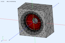
You can place a woofer inside a waveguide using Source.Contours. I attached a config file that does it with a coaxial driver as an example.
Attachments
Here is a stab at measuring the BMS 4552nd parts. Take the angles here with a grain of salt however the angle of the plastic is for sure more narrow than the steel. There is an ~0.3mm lip between the plastic and steel parts that accounts for the 0.6mm diameter difference between them. I don't know if this helps with any of the other BMS neo CDs but I would surely like to see an optimized adapter for this one (because I have several of them...) 😀

I was curious about the effect of the central part of the BMS phase plug.
So I've tried a few different geometries, basically the heights of a central cone -
For instance, 0 and 8 mm:


These are the corresponding acoustic impedances:

Assuming the simulation is correct, it would seem that the shape of this detail is pretty important for the HF efficiency of the driver.
It has absolutely no effect on wavefront/directivity below 20 kHz, as it's still very small relative to the wavelengths involved.
So I've tried a few different geometries, basically the heights of a central cone -
For instance, 0 and 8 mm:
These are the corresponding acoustic impedances:
Assuming the simulation is correct, it would seem that the shape of this detail is pretty important for the HF efficiency of the driver.
It has absolutely no effect on wavefront/directivity below 20 kHz, as it's still very small relative to the wavelengths involved.
Last edited:
Honestly, I don't remember, like at all. I think you will need to apply some creativity.On the rossi, did you cut and remove the section of the gasket that is occupied by the insert and left the rest as is? I'm about to do the operation.
No, and as far as I can recall, it didn't work quite well with the only driver tried (some big RCF?). A more typical (only-expanding) adapter worked better, I think. We're still kind of shooting in the dark here, because the full models of the actual drivers are still not part of our (simple) simulations. That's quite a big leap to make.@matbat I was looking at the T520-36-EXT-1 extension that shows a LF extension to 320 hz - do you have any particular compression drivers you've used with this setup that works well? This might just check all the boxes I need for a particular design I'm working on at the moment.
OK - I did.Honestly, I don't remember, like at all. I think you will need to apply some creativity.
I cut a circle in the CD gasket and removed it so that the insert could meet the metal of the CD. And I put the bug screen between the horn mount and the insert - worked perfectly. So no wasp nests 🙂
//
Hi CinnamonRolls
cool template to start with. Thank you!
Unfortunatrly now 2 weeks off and no workstation near me 😱. Difficult to make holiday from audio hobby...
cool template to start with. Thank you!
Unfortunatrly now 2 weeks off and no workstation near me 😱. Difficult to make holiday from audio hobby...
OK - I did.
//
Does this mean that it is that little pointy cone that is responsible for the peak in the response between 10 and 20khz on most all of the BMS cds? If so it's too bad that park isn't easily removable for the purpose of optimizing its shape. I'm tempted to possibly sacrifice a diaphragm to get some better measurements and play with the shape of its guts.I was curious about the effect of the central part of the BMS phase plug.
So I've tried a few different geometries, basically the heights of a central cone -
For instance, 0 and 8 mm:
View attachment 1396544 View attachment 1396543
These are the corresponding acoustic impedances:
View attachment 1396541
Assuming the simulation is correct, it would seem that the shape of this detail is pretty important for the HF efficiency of the driver.
It has absolutely no effect on wavefront/directivity below 20 kHz, as it's still very small relative to the wavelengths involved.
With fresh eyes and mind this morning I refined some of my measurements of the diaphragm part and would now call the exit angle of it 19 degrees.
That was my first thought as well, but I don't know, the simulation is still overly simplified.
- I think that it shouldn't be difficult to get rid of the central part by milling it off from the back side. The question is if there's anything to be improved - I tend to believe that the BMS engineers knew very well what they were doing. Maybe with the slow-expanding throat it's a bit different, I really don't know.
- I think that it shouldn't be difficult to get rid of the central part by milling it off from the back side. The question is if there's anything to be improved - I tend to believe that the BMS engineers knew very well what they were doing. Maybe with the slow-expanding throat it's a bit different, I really don't know.
Last edited:
- Home
- Loudspeakers
- Multi-Way
- Acoustic Horn Design – The Easy Way (Ath4)