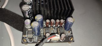
Here is the building thread of my tpa3255 amplifier.
The board is bought on Amazon and the power brick is 36V 6A . The case is bought at Audiophonics, France.
Some modifications gonna be made, but this it the result so far.

The board is bought on Amazon and the power brick is 36V 6A . The case is bought at Audiophonics, France.
Some modifications gonna be made, but this it the result so far.
Suggestions:
You overlooked that this case needs a subchassis. An aluminium sheet 1.5 or 2 mm screwed to the lower side of the left/right vertical bracket with 4 x M4 bolts, nuts and washers. There is a few millimeter space to shove the sheet between so it will lay on the brackets mounting holes. The subchassis gets the mounting holes for the PCBs etc.
This way no ugly and possibly sharp screws stick out of the bottom. Drilling an aluminium subchassis is easy compared to drilling the steel upper and lower cover. The case can otherwise not be reused either as it has holes for a specific board. Also the space below the subchassis is an excellent cooling air channel. Just drill the cooling slots at the right places where air can enter and where air(flow) is needed. The air can enter via holes in the lower side of the back panel and the warm air can leave via holes at the upper side of that same back cover. This way the amplifier has non visible passive cooling with chimney like air draw.
Also never place an amplifier board in the middle as no space is left at either left or right side for a (future) power supply, relay based volume control (open input power amplifiers may be regretted one day), speaker protection board etc. It works way better to keep loudspeaker outputs at one side with the 230V IEC inlet near the outer corner and the inputs at the other side.
BTW you wil regret this as it is a system choice. About the only place where DC blocking caps are very useful as DC fuses is exactly there.I will also bypass the two input 10 uF capacitors , my dac has dc protection at rca out.
Last edited:


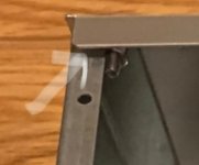
No RCA connectors fixed at the amplifier, -they havent arrived yet so I direct soldered the RCA cable and used plastic stop nuts to keep the cable fixed. This will probably going to be changed , but at the same time - the best connector is no connector so who knows 😀. When my 4 WIMA 1uF output filter capacitors arrive I have to disable the board anyway.
This modification will lower the distortion significantly , measuring better than an Aiyima a07.
Here is Audiogue:s measurement on this tpa3255 board , the distortion is much lower with the WIMA caps.


This modification will lower the distortion significantly , measuring better than an Aiyima a07.
Here is Audiogue:s measurement on this tpa3255 board , the distortion is much lower with the WIMA caps.
Last edited:
Now its time to listen, it will be interesting to hear how good or bad it is - Im not gonna sugar coat anything and compare to my reference amplifier, a gain modified Hypex ncore 125 from Audiophonics.
I have two Aiyima a04 tpa 3251 ( one modified ) so this 3255 might be more powerful.
After initial listening I will change the input IC from ne5532 to opa1612 ( on extra adaptors ) and also try with lm4562.
Last edited:
The spot where the aluminium subchassis is shoved in (suppose this is the bottom side) or at its upper side which IMHO is even better but requires more precise cutting of the sheet. Otherwise it will either jam or the M4 holes will be too close to the edge.
Of course this can only be done with the black covers detached. There should be enough space below it for airflow. I used to mill ventilation slots in the back cover for fresh air as mine had fully closed upper and lower covers. Yours has ventilation slots (overlooked that initially) so only holes in the subchassis are needed at the hotspots.
I used these casings a lot in the past but then they could not be ordered anymore. Do you know their product number and brand name?
Attachments
Last edited:
The caps are low enough on that board where you can easily flip and mount a solid alloy heat transfer block/plate to the chip, then mount that to the case bottom. JAT.
Steel and rough. Probably worse than the way it is now. Fans are 666 but mounting a temperature switched 60 x 60 or 80 x 80 mm (better, if it fits) one "just in case" won't hurt. To prevent overheating such a measure is acceptable I think. Or have it switched with a toggle switch at the front.
For forced air the existing ventilation slots are probably too small. Then a rectangular hole for the fan must be cut in the back and probably a few holes at the bottom must be drilled which is a pity as that is steel is tough and it will look ugly (I know as I made that mistake myself 🙂). Again that subchassis would have made that way easier. With the possible maximum power of TPA3255 I think about 50 to 60W will be converted to heat that must be given to the environment. One needs a larger casing and take heat disposal into account. The worst case principle.
Mounting the thing I won't call by name again would mean the 4 now drilled holes could be enlarged to 10 mm cooling vents but.....don't be surprised the larger drill will jam and the casing will fold like a sheet of paper. Very slow drilling with a fresh and sharp drill and oil added and the cover clamped (NOT in hand!) with scratch preventing stuff.
Last edited:
First 5 minuters impression, sound is good , no popping sound when cutting the power with board, or turning the power on with the powerbrik . No noise at all . Good news.
After 5 minutes - I can conclude that the sound is good , but not as good as my Hypex ncore. The bass is a little detached and the treble is less smooth. Lets see If swapping the jrc 5532 for something other can be better sounding ? Lets try opa1612….


After 5 minutes - I can conclude that the sound is good , but not as good as my Hypex ncore. The bass is a little detached and the treble is less smooth. Lets see If swapping the jrc 5532 for something other can be better sounding ? Lets try opa1612….
5 or even 50 Minutes is by far not broken in. Takes at least a few hours, possibly days. Opamp rolling should be done when it is broken in and then giving the opamps also enough time to settle. Multiple day venture normally.
Could you tell what brand and type or series name the casing has? Went to my stock room and I have an incomplete one and a full aluminium one left but no brand name anywhere.
Could you tell what brand and type or series name the casing has? Went to my stock room and I have an incomplete one and a full aluminium one left but no brand name anywhere.
Last edited:
Thanks for input about burning in. My experience is that ne5532 never sounds better than an opa1612 , so I swapped it after 5 minutes. It really sounds decent now, better bass, better hights , less cold. I guess that the sound, as you say, will improve even more after a day or two . So no final judgement from me about the sound before at least a week and I will also do the 4 WIMA 1uF cap mod.
The case from audiophonics were bought 5 years ago and has been unused in the basement. I dont have the brand name of the case left, but is has 4 ventilation slots -2 at the top lid and 2 with the same shape under the box.
The case from audiophonics were bought 5 years ago and has been unused in the basement. I dont have the brand name of the case left, but is has 4 ventilation slots -2 at the top lid and 2 with the same shape under the box.
Maybe you can change input caps to better (I'm using Elna Silmic, and replaced all of electrolitics).First 5 minuters impression, sound is good , no popping sound when cutting the power with board, or turning the power on with the powerbrik . No noise at all . Good news.
After 5 minutes - I can conclude that the sound is good , but not as good as my Hypex ncore. The bass is a little detached and the treble is less smooth. Lets see If swapping the jrc 5532 for something other can be better sounding ? Lets try opa1612….
View attachment 1384043View attachment 1384044
Attachments
Ah, feket 663, you do have the same board 🙂 . Thanks for input.
Did you reckognize any sound change for the better replacing the dc block caps at the line input ?
After swapping the ne5532 to opa1612, the sound went better but still a little to bright compared to my Hypex ncore. Is this the sound of a card not burned in yet, or the 4 output capacitors generating more distortion from 2 KHz and above?
Last edited:
- Home
- Amplifiers
- Class D
- TPA 3255 building thread