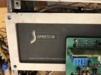
Hi,I have a stripped Spectral DMA 100 amplifier,need help finding power supply specs for both driver and output.
I have a need to build power supplies as the chassis is missing both transformers……maybe use the chassis,I do have a Diyaudio 5U chassis new in the packing…I have been saving it for a new project,or,if the transformers needed can fit the original chassis,maybe use the Spectral case.
all outputs verified ok.
The boards appear to be prototypes,there is no serial number sticker on the back of the case….found at the Alameda Antique Fair,SanFrancisco in 2017…..
thanks,Dave Grady
Attachments
It won't be a DMA 200 /2 or 3 instead?
It seems that some parts are missing and that it has suffered some trauma.
It seems that some parts are missing and that it has suffered some trauma.
Possibly,have not gone far enough to know,figure out first the power needs.I can bench the module and backwards figure the power,just thought a member might have the specs first…the trauma next to the ground post was there all along,the L brackets were removed to inspect,does not intrude to any traces.

That is one of maybe two or three Crosby mod DMA 100 gen one. It predates the DMA 50.
Unlike the later units that was a fully balanced bridge tied load design from the start.
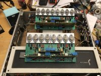
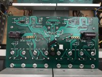
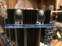
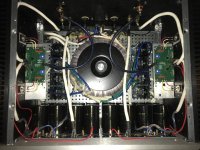
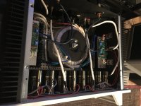
However the boards appear to be fully modified with all the tweaks. There is a heat sink tunnel down the middle with a fan running at a low speed.
Its possibly the best amp Spectral ever made when modified.
Unlike the later units that was a fully balanced bridge tied load design from the start.
However the boards appear to be fully modified with all the tweaks. There is a heat sink tunnel down the middle with a fan running at a low speed.
Its possibly the best amp Spectral ever made when modified.
Thanks for the reply….where do I go from here,need at least help with power…….what mods apply to these boards…
thanks again!
Dave
thanks again!
Dave
I would break down this project into several tasks:
1) lets identify what you have-
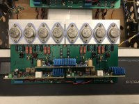
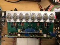
The boards are the Crosby mod version, the Spectral boards never had the thrd regulator PCB in the middle.
Do you have the wiring harness?
Do you have the folded sheet metal that held the transformers? Pictures of the chassis from top and bottom will help.
2) We should set up to test the boards outside of the chassis. You will need two bench supplies- one centertapped for the driver board and one for the outputs. In that amp since its BTL the output supply has no center tap.
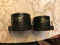
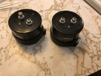
3) Once the boards are verified (mods much later) we can then look at the power supply. It was two large transformers, for the outputs plus rectifier blocks and caps and it would have two small similar supplies for the driver boards. I have the DMA 50 version here and I hope to open it up later this week and note the transformer voltages. What you have is essentially two DMA 50's with mods in one box.
1) lets identify what you have-
The boards are the Crosby mod version, the Spectral boards never had the thrd regulator PCB in the middle.
Do you have the wiring harness?
Do you have the folded sheet metal that held the transformers? Pictures of the chassis from top and bottom will help.
2) We should set up to test the boards outside of the chassis. You will need two bench supplies- one centertapped for the driver board and one for the outputs. In that amp since its BTL the output supply has no center tap.
3) Once the boards are verified (mods much later) we can then look at the power supply. It was two large transformers, for the outputs plus rectifier blocks and caps and it would have two small similar supplies for the driver boards. I have the DMA 50 version here and I hope to open it up later this week and note the transformer voltages. What you have is essentially two DMA 50's with mods in one box.
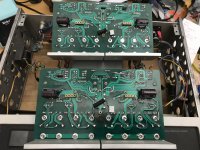
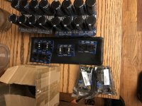
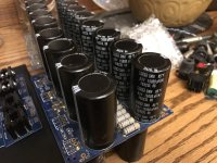
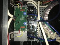
Thanks again for the reply,here’s a comprehensive set of images…..all wiring harnesses intact,the driver leads to one of the smmall power transformers was snipped and is still attached to the smaller transformer,the other lead was just pulled off the transformer pins.
Does the stock harness look originally like this,or is this part of the mods,as most images of Spectral products show very neat wire harnessing….how much output voltage do I need to verify the boards,do I need to heatsink the outputs?
Does the stock harness look originally like this,or is this part of the mods,as most images of Spectral products show very neat wire harnessing….how much output voltage do I need to verify the boards,do I need to heatsink the outputs?
Attachments
-
 image.jpg378.9 KB · Views: 170
 -
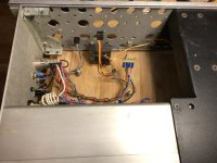 image.jpg398.8 KB · Views: 159
 -
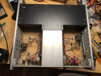 image.jpg517.8 KB · Views: 159
 -
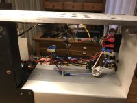 image.jpg337.4 KB · Views: 151
 -
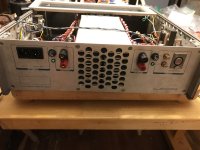 image.jpg379.2 KB · Views: 150
 -
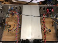 image.jpg484.7 KB · Views: 150
 -
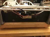 image.jpg351.2 KB · Views: 141
 -
 image.jpg491.9 KB · Views: 152
 -
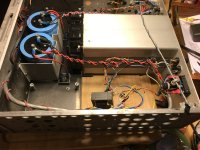 image.jpg490.9 KB · Views: 149
 -
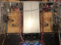 image.jpg485.2 KB · Views: 160
 -
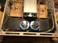 image.jpg497.7 KB · Views: 178
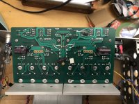
Hi,also wanted to ask about the trim pots on the boards,how do I adjust offset And bias?
thanks again,Dave
thanks again,Dave
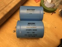
Check the ratings on the big caps. I think you need 50V DC under load for full performance. So that would be 50V + 1.4V rectifier drop +52V peak or 36V RMS. And a max RMS current of at least 10A.
These may work, but may be too big: https://www.ebay.com/itm/2253103138...6vMckMLc5YtrSFhgL46FqEKw==|tkp:Bk9SR8T7zLvDZA
These may work, but may be too big: https://www.ebay.com/itm/2253103138...6vMckMLc5YtrSFhgL46FqEKw==|tkp:Bk9SR8T7zLvDZA
This is another alternative: https://www.ebay.com/itm/2554686474...MC0q7k6YeNXkewon7lfKeXT0E=|tkp:Bk9SR8T7zLvDZA
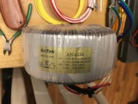
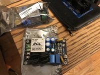
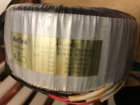
So,is it ok to strap all the secondaries together?.
1000va,strapped for one secondary….what do you think…?
1000va,strapped for one secondary….what do you think…?
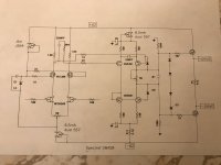
That schematic is interesting but not quite right. Now I need to open mine to check the voltages. The driver circuit, what is illustrated, is similar but not what is drawn. I'm traveling until next week so unable to check details. I can also write up the test sequence to go from PCB's to a complete amp. I will review the voltages again just to be sure.
Why someone would remove the transformers is beyond me.
Why someone would remove the transformers is beyond me.
Hi,thanks for the reply…The schematic is the only reference to Spectal products on Google…I agree on the mystery…when I saw the amp at the flea mkt,I expected it to be heavy,went to move it and it slid on the ground,with no mass from the transformers….oh well…thanks again for the help,it will be great to complete it!
Thanks Again,,Dave
Thanks Again,,Dave
- Home
- Amplifiers
- Solid State
- Spectral DMA 100 Help needed