How many volts AC go to this amplifier when using the 200W bulb?I am already using 200 watts bulb in series for over current protection. If use 100 watts bulb then capacitor charging will take more time to fully get charge and has to wait longer after switch ON the amplifier. See attachment.
Once again the startup diodes are on the back of the power output board P649 and not on board P647.
And because this is an amplifier from the mid-70s of the last century, a recap of the electrolytic capacitors is probably necessary.
And because this is an amplifier from the mid-70s of the last century, a recap of the electrolytic capacitors is probably necessary.
Sir,troubleshooting procedure to start up the power supplies using a 4.7k resistor.
No idea where to use this 4.7k R to be used. Please guide.
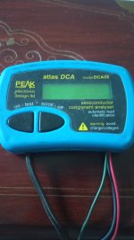
This amp is in very good condition no scratches non of parts or electrolyte capacitors been used. I removed and measured and found deviated from, capacitor printed specifications. 100v 2.2uF printed on cap. I measured with fluke meter and found 2.96uF similarly. Another capacitor which has printed value 100v, 100uF. I measured 180uF.
It means big deviation. This is not the result from one meter. I used three meters.
After this I measured one new cap which was with me, gives measured and printed uF same means need replacement. I don't have good caps. It means I have to import from Japan or China.
Actually after discussion with you I bypass the series bulb and put direct, because I was sure of no fault. I did not measured the AC voltage going to transformer but the DC that is finally out from main two capacitors is as per given voltage and that is Red +55/ grey -55 reference to black, that is directly leading to power transistors via C11M ~ C18M. This means series 200 watts bulb not creating problem.How many volts AC go to this amplifier when using the 200W bulb?
Oh really sorry. I did mistake. I should go to power board P649 instead of P647. Let me check. 🙄power output board P649 and
The advice is to use high-quality capacitors from, for example Panasonic or Nichicon.
Judging from the photos, this is one of the first versions of the L100.
Judging from the photos, this is one of the first versions of the L100.
I have no idea but you have the knowledge and you can better judge.Judging from the photos, this is one of the first versions of the L100.
Attaching picture of board P649. Only boat diode (SV03) seen combination of three diodes with temp composition.power board P649
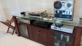
I have another Luxman filling the gap of L-100. This Luxman L-230 also sounding great with new box pack Linton recently imported from UK through dealer. I tested many amps but best match to my understanding is Luxman L-230. I also tested Macintosh new 275 tube but still Luxman is on top. I don't know why?. There is another my friend amp is Musical Fidelity A1. Great sound, may be little better than Luxman L-230. Now looking for Quad 303 power. Passive pre I have.I have no idea but you have the knowledge and you can better judge.
Attachments
Nichicon may be better than Panasonic but never tested the ESR and compare. Nichicon is dedicated for capacitor manufacture to my knowledge.The advice is to use high-quality capacitors from, for example Panasonic or Nichicon.
My question. If unplug both Left & Right connector C11M>>>C18M from board PB649 will the voltage (+ - 48) appear on C07S>>>>C10S of PB647.
I am asking it because I don't want to put danger on these TO3 transistors and driver boards. 😇
I am asking it because I don't want to put danger on these TO3 transistors and driver boards. 😇
See bottom of page 6 of the service manual:No idea where to use this 4.7k R to be used. Please guide.
Its important to study that whole page 6 very carefully to understand the power supply. Then look at the real circuit on page 17 of the service manual. The transistor numbers on page 6 and page 17 are the same. Locate Q903 and the other transistors on both schematics, Locate the zener diodes on both schematics. When you understand what the service manual is trying to tell you, then we can proceed.

Thanks a lot for new guideline. I think it will take little time to follow your instructions.Its important to study that whole page 6 very carefully to understand the power supply. Then look at the real circuit on page 17 of the service manual. The transistor numbers on page 6 and page 17 are the same. Locate Q903 and the other transistors on both schematics, Locate the zener diodes on both schematics. When you understand what the service manual is trying to tell you, then we can proceed.
If you look at the photos of the L100 restoration on the internet, you will see the differences and modifications on board P649. There you can see where the diodes are placed in the newer models. These diodes ensure that the power supply on board P647 is started.
The voltages that should come from board P647 are approximately plus and minus
58 volts.
Are all alternating AC voltages present on board P647?
In power supplies I always use capacitors with a low ESR.
The voltages that should come from board P647 are approximately plus and minus
58 volts.
Are all alternating AC voltages present on board P647?
In power supplies I always use capacitors with a low ESR.
I did injected pulse voltage manually through 4.7k in the power supply board as per your suggestions. It triggered the amplifier relay energised and blinking of light on the front panel goes ON. Means amp goes on.
Note: It send touch pulse only. I tested three times. It goes on every time but not automatically but through voltage pulse injection.
Now amplifier is ON but - 4 VDC appear on binding post of both speakers. It means may be amplifier power supply is ok but some other problem.
Driver stage PB649 is ok I checked all transistors.
Anyhow a major work done today. Now trouble shoot other stages.
Now I checked voltage on C07S>>>>C010 on the board PB647
voltage appears DC 51 (red-gray wires) not 48 volts
voltage appears DC 51 (red-gray wires) not 48 volts
Hi,
Just tested power transistors TO3 part no 2SD287B is faulty and open ( Base to Collector, Base to Emitter, No junction drop like 0.5 volts on meter ) and this faulty transistor is parallel with similar part no 2SD287B. It is in the left channel. very difficult to find from market.
Just tested power transistors TO3 part no 2SD287B is faulty and open ( Base to Collector, Base to Emitter, No junction drop like 0.5 volts on meter ) and this faulty transistor is parallel with similar part no 2SD287B. It is in the left channel. very difficult to find from market.
- Home
- Amplifiers
- Solid State
- Luxman L-100