What do you guys think? I usually put a small say 220R on grid of EL84. What about 6N3P?

Designed by Gerd Reinhöfer †
Found on this webpage: https://www.jogis-roehrenbude.de/Verstaerker/EL84.htm
Uses (Output) Plate/Anode to (driver) cathode feedback.
Lowers distortion.
Worsens PSRR. Ergo you need a very clean power supply.
Designed by Gerd Reinhöfer †
Found on this webpage: https://www.jogis-roehrenbude.de/Verstaerker/EL84.htm
Uses (Output) Plate/Anode to (driver) cathode feedback.
Lowers distortion.
Worsens PSRR. Ergo you need a very clean power supply.
Last edited:

Yes, both. Consider the screen also.
Since there's no overall feedback including the OT, you can set their values where you want.
Somewhere between 1k and 10k, located very close to the tube socket pin.
Unless you have problems with local RF pickup, when they may need to be larger.
Somewhere between 1k and 10k, located very close to the tube socket pin.
Unless you have problems with local RF pickup, when they may need to be larger.
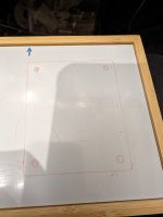
Progress for the evening. Drilled holes for the sockets and fitted them. Started soldering. Grid stoppers for the 6N3P done. Screen and grid stoppers for the EL84: todo.

No problems in the 20+ years. But I always wonder about some ultra high frequency oscillation or something.Unless you have problems with local RF pickup, when they may need to be large
Easily one of the better circuits I've seen lately. Is R9 too small? Maybe half? I would argue for C1 to be smaller by a factor of maybe three, but just my opinion. Grid stops are always a good idea, no penalties, no foul.
All good fortune,
Chris
All good fortune,
Chris
I thought it was low too. Closest I had was 150R. Wonder of it is a mistake? Should I go to say 270R or so? Or level it as is.
I wrote off the cuff, and was, as usual, too conservative. 130R is the factory recommended value and gives full rated dissipation. I'd (still) be a little more conservative, but was wrong to question your choice.
Always the best to you and yours,
Chris
Always the best to you and yours,
Chris
In the schematic the 6N1P plate resistors read 33K, but in the picture you use 22K. changed your mind?
You might consider a high value resistor grid to ground on the 6n3p in case the pot wiper ever opens up.
Will do. I'm skipping the pot. And will add a high value resistor grid to ground as you suggest.
If you go with 150R and experience problems running EL84 (which is unlikely, but I‘m curious) you could try it with 6P15P, which requires less bias than EL84. At your supply voltage 6P15P should work well (watch the 6P15P screen dissipation though).Nevermind...I'll stick to the 150R..
Last edited:
At ~258 V across the EL84 and cathode resistor of 150 ohm it a reduction in screen voltage is probably not needed. If you do try 6P15P you may need a screen resistor to monitor screen current.Why is there no attempt to lower the screen voltage in the schematic in post 1?
Progress. PSU will be built on same chassis size/look. Will glue them together.


Nice work as always, Bas. I always look forward to seeing your builds progress.
- Home
- Amplifiers
- Tubes / Valves
- Another SE EL84. Following this schematic. Grid stoppers yay or nay?