Happy New Year, one and all....
My project for a 6AS7 PP stereo amplifier is nearing a reality, however when considering various design options I have a dilemma: What type of circuit should I use as a phase splitter? I've read various pros and cons about several types and I must admit, I'm none the wiser....
The design parameters are:
The overall design is 1-off 6SL7 plus 2-off 6N1P plus 2-off 6AS7. DC supply will be solid state rectified. This is for an existing chassis that I want to re-purpose using the valves stated.
Constructive comments sought from you wonderful people out there....
My project for a 6AS7 PP stereo amplifier is nearing a reality, however when considering various design options I have a dilemma: What type of circuit should I use as a phase splitter? I've read various pros and cons about several types and I must admit, I'm none the wiser....
The design parameters are:
- I want to use a single 6N1P double triode to be phase splitter/driver for the PP 6AS7 power stage;
- the design will use a single positive B+ supply of between 250v and 290vdc, so no negative supply available;
- each triode in the 6AS7 will be Cathode biased using a 1k2 resistor and 100uF electrolytic, hopefully to achieve a little over 80mA plate current per triode;
- some negative feedback would be ideal;
- I understand that 6AS7 needs a wide voltage driver swing to get a useful power output (aim is for ~12w per channel);
- the input pre-amp would be one side of a 6SL7;
- the usage is for hi-fi so an option with low inherent distortion is required.
The overall design is 1-off 6SL7 plus 2-off 6N1P plus 2-off 6AS7. DC supply will be solid state rectified. This is for an existing chassis that I want to re-purpose using the valves stated.
Constructive comments sought from you wonderful people out there....
Last edited:
As said, we need more info. What is the source signal level? how much gain do you need from that level to each grid?
Going off what little you've given-
A 6N1P will only give ~30x gain in most applications, even with a bypassed cathode. in a differential pair the max theoretical gain is cut in half. half of a 6sl7 feeding into a 6n1p differential pair would be useful here. A concertina will not be able to swing the needed voltage so a differential is about your best bet.
With how variable the 6AS7 can be you are looking at anywhere from 75~90 volts of bias. This will require twice that swing per grid for full output, which will be difficult to achieve at 250~290 volt supply using the 6n1p, at least with tolerable distortion. Just doing some quick sims, you will already be over 6% total distortion when swinging 100 volts off of one 6n1p triode section.
The 6AS7 is a huge challenge to run at higher voltages- and in my extensive experience with them they make higher THD up there anyway, giving very little reason to do so- A supply voltage from 130-175 is the sweet spot for them- take the 7~8 watts you get, and the driving requirements are much less.
100 volts, 100mA, ~33 volts bias is my favorite place to run them. This is very easy to drive with commonly available front ends, and gives lower THD than high volt, higher complexity solutions. Remember- these are regulator/pass devices- they are optimized for lower voltage drop at moderately high current.

Great - thanks for the responses and comments so far. I had opted for 6N1P for two reasons: I've got a noval socket to fill and the 6N1P can work with high B+ to give the voltage swing to drive 6AS7, from what I've read elsewhere. (My other option is MOSFET phase splitter, but I'd like to stay with a noval).
Running at 130-175vdc in PP is that 7~8 watts per valve?
The input source would be standard RCS phono hence using the SL gain of around 70.
I've seen plenty of circuits using a B+ of 250-290vdc for 6AS7, but I guess they didn't comment on the THD. How effective is negative feedback with higher B+?
Running at 130-175vdc in PP is that 7~8 watts per valve?
The input source would be standard RCS phono hence using the SL gain of around 70.
I've seen plenty of circuits using a B+ of 250-290vdc for 6AS7, but I guess they didn't comment on the THD. How effective is negative feedback with higher B+?
it all depends on gain. if you can swing lotsa volts at low enough distortion you can afford to trade off that swing for lower THD by sacrificing some gain. However, you may end up with worse distortion performance overall by pushing the driver stage harder into a non-linear region of its curves- or negatively impacting the overall nature of the distortion. This is where higher supply voltages up into the ~400 or so range can help- you get more headroom for those higher swings and start cleaner to begin with. low or medium mu triodes with low plate resistance can generally swing more volts at lower THD, just with less overall gain. The 6n1p isn't necessarily a bad choice overall, but just the nature of your supply voltages limit how much you can do here.
Ok, lots of interesting scenarios here... If I look at the Power Tx I've got, that limits me to the 250-300vac at 250mA on the secondary which will obviously dictate some of the options. There's two windings so that's in series and I guess gives me around 270vdc after SS rectification.
I came across these phase splitter/inverter circuits for 6N1P and 6N2P. Courtesy of:
https://web.archive.org/web/2007091...op/russianotes.htm#6N1P /6N2P How to use them
https://web.archive.org/web/2007091...op/russianotes.htm#6N1P /6N2P How to use them
Attachments
In case you want to drive 6AS7G's with a phase splitter, then you have just one choice; the LTP. With or without bootstrap from the UL-taps of output transformer.
- I want to use a single 6N1P double triode to be phase splitter/driver for the PP 6AS7 power stage;
250...290 V is far from optimum. The optimum anode voltage of 6AS7G is 250 V (max. suggested by specs.). Cathode bias require some 120...125 V, so +Ub should be 370...380 V. Then each triode-halve will take 50 mA.
- the design will use a single positive B+ supply of between 250v and 290vdc, so no negative supply available;
12 W is possible, but required drive voltage is 250 Vp-p (i.e. 2 x Ubias)
- I understand that 6AS7 needs a wide voltage driver swing to get a useful power output (aim is for ~12w per channel);
For best linearity (lowest THD), take 5k output transformer.
- the usage is for hi-fi so an option with low inherent distortion is required.
That is a good idea. 6AS7G has inherently quite high 3rd harmonic distortion (in PP).
- some negative feedback would be ideal;
Second for input transformer. Preferably a bifilar wound transformer to insure proper balance between windings.
Or, if you are lucky enough to have an audio source with balanced output, then you do not need a phase splitter at all.
Still- the phase splitter is not the big issue here- the supply voltage is. Implementing a good phase splitter is trivial as long as a few basic requirements are understood and taken into account. The main issue here is that 300 volts supply will not allow enough swing to reach the needed drive voltage for the 6AS7G when used as the OP desires- With typical audio tubes you will generally barely reach 1/3 of the supply voltage if you are lucky and nail the details perfectly. When your tube is biased at ~125 volts, you need to swing twice this voltage to reach full output. 250 volts is a ton of signal. at 300 volts good luck even getting halfway there with tolerable THD.
Quick estimate for a 300 volt supply (likely less, after filtering, but that's not too important here for the pint I'm trying to make) is that the 6N1P is not going to perform as intended here- you will be lucky to get 100 volts swing at 2~3% THD- which will be mostly odd harmonics. Jumping up to 400 volts supply and adjusting the operating points will cut that number in half for the same output. Also, none of this even accounts for voltage headroom for a tail resistor, although a tail CCS would save you the trouble and eat up less supply voltage. Even with a balanced input to the LTP I would run a CCS to force balance to prevent intermodulation distortion, which can be very gross when dealing with this sort of voltage swing.
This is why many applications of the 6AS7G will run them at lower supply voltage for less bias, implement more complex bootstrapping for swing, or will run a separate higher voltage PSU section for the driver/phase splitter stages.
I prefer to run them low and hot, and take what i get for this reason. Lovely tubes, but the juice isn't worth the squeeze to put all the work in to run them in a way that they are so much of a challenge to use. If you can handle ~7 watts of output getting them to 100~125 volts across the plate, and running them at 10 watts of dissipation works great- and can be driven off of a typical phase splitter arrangement with no fancy or convoluted additional work.
Also- an easy trick for higher voltage driver stages- run a lower voltage transformer backwards off of the filament supply, rectify the voltage off of the original primary, and stack that on top of your original supply after you tap off the run to the power stage. Accounting for losses this will add 100~150 volts or so for more driver headroom. A lower power filament voltage transformer works great for this.

I think that's a lovely start, some quick notes, however-
The input capacitor to the first triode in your long-tailed pair can be made a decade smaller in value, as the grid resistor is bootstrapped by the tail resistor. .01Uf would work well.
The plate resistor for the second stage will likely need to be adjusted in the actual built circuit, in order to bring the output swing equal between each plate. You have a good starting point so far on value. Also- if you replace the tail resistor with a simple current sink you can make both plate resistors equal. This will also give you more headroom for lower THD swing at higher output.
As drawn, I do not think you will have enough swing to bring the 6AS7G outputs to full output. And once you are close to the differential pairs full capability you will have high THD. Hard to tell exactly where that limit is with what I have access to at the moment, but figure some 75-90 volts peak before some 5% or so THD per 6N1P plate. This will be fairly audible and it will sound somewhat compressed depending on the balance and if it falls more 3nd or 3rd harmonic. The lack of swing will be brought even lower by the additional global negative feedback.
Personal suggestion-
Build that circuit as you have shown. Adjust the plate resistors for as perfect balance as you can (or swap the tail for a current sink) and then measure the output. Find what output swing gives you the THD you feel comfortable driving your output stage with. From here, adjust the supply voltage and bias resistors for the 6AS7G output stage to match the available signal swing. From here hook up the negative feedback, make sure it's stable and still reaches full output. If all good, call it done and enjoy, without worrying too much about complete power output.
Build that circuit as you have shown. Adjust the plate resistors for as perfect balance as you can (or swap the tail for a current sink) and then measure the output. Find what output swing gives you the THD you feel comfortable driving your output stage with. From here, adjust the supply voltage and bias resistors for the 6AS7G output stage to match the available signal swing. From here hook up the negative feedback, make sure it's stable and still reaches full output. If all good, call it done and enjoy, without worrying too much about complete power output.
A center tap for phase splitting is not always necessary. Just two equal value resistors can form a virtual center tap to ground on the secondary and you can get just as good balance like this one.Second for input transformer. Preferably a bifilar wound transformer to insure proper balance between windings.
Shame you haven't got a negative supply your LTP would benefit. A little 50v or 0-24v 0-24v tfmr could be tucked under the chassis. With a CCS running off - 60 to 80v your LTP would have more V swing as you could drop more V across the anode resistors. I might have something, drop us a PMif interested. Think I have some pare CCS boards too.
Andy.
Andy.
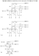
Here is a bit of a simulation, using 290V for B+. I added an LM334 to be able to use most of the B+ to the 6N1P while keeping the LTP properly balanced. I'd prefer something like a 6N6P to be able to ramp-up the LTP current. I'm not sure how good is the 6AS7 model I used though.

Fourier components of V(out)
DC component:-0.0210545
Harmonic Frequency Fourier Normalized Phase Normalized
Number [Hz] Component Component [degree] Phase [deg]
1 1.000e+3 1.272e+1 1.000e+0 90.54° 0.00°
2 2.000e+3 3.374e-3 2.652e-4 -174.34° -264.89°
3 3.000e+3 1.207e-2 9.482e-4 -41.92° -132.46°
4 4.000e+3 5.621e-3 4.418e-4 7.40° -83.15°
5 5.000e+3 4.158e-3 3.267e-4 -102.42° -192.97°
6 6.000e+3 3.857e-3 3.031e-4 -164.88° -255.43°
7 7.000e+3 2.009e-3 1.579e-4 -44.34° -134.89°
8 8.000e+3 2.580e-3 2.028e-4 18.38° -72.17°
9 9.000e+3 1.717e-3 1.350e-4 122.30° 31.76°
Partial Harmonic Distortion: 0.120313%
Total Harmonic Distortion: 0.177630%
power_output: AVG(i(rl)*v(out))=10.1199 FROM 0 TO 0.025
Hi Andy,Shame you haven't got a negative supply your LTP would benefit. A little 50v or 0-24v 0-24v tfmr could be tucked under the chassis. With a CCS running off - 60 to 80v your LTP would have more V swing as you could drop more V across the anode resistors. I might have something, drop us a PMif interested. Think I have some pare CCS boards too.
Andy.
Thanks for your comments. The secondary windings are arranged 0 - 125 - 150 such that I can series or parallel. If I connected in series and rectified 125 - 0 - 150 - 125 - 0 that could give me a secondary AC of 275v at 250mA and a 25vac winding using 125 - 150 I could create a negative supply from?
What design do you have for your CCS? Discrete or LM317 type?
- Home
- Amplifiers
- Tubes / Valves
- HiFi phase splitter - "best" design option?