Over the next few months, I'll be building the DynakitParts ST-35 with their bias control upgrade and choke. I also will be doing some other simple and inexpensive upgrades, whether "necessary" or not. I have opted not to use "enhanced fixed bias" circuitry, choosing instead the bias kit from DynakitParts that allows adjusting each tube individually.
It's a very nice kit, complete with everything needed except tools, solder, and tubes. It even comes with a free Dynakit ball cap. https://www.dynakitparts.com/shop/st-35-kit-120-vac/

I did purchase the optional tube cage as shown above, but I doubt that I will ever use it. Some future owner might though. I might open up the solid sheet metal sides and install matching perforated metal if I can get a small quantity of it.
A discussion of tube lifespan and possible power supply mods is here: https://www.diyaudio.com/community/threads/dynakitparts-st-35-power-supply-mods.398189/
The first "upgrade" was to purchase a 14/3 power cord. The kit comes with an adequate 18/3 power cord with inline rocker switch, but I will be installing a switch on the chassis instead, ideally a rocker switch on the front panel if I can find one that will fit.
Today I mounted four larger rubber feet to the bottom of the chassis. The ones that come with it are very, very small, making it hard to lift or move the amplifier because you can't get your fingers under it. I just happened to have four new rubber feet from some other project in my parts box and some screws and washers that fit, so that worked out great.
The two power supply diodes look a bit skimpy by today's standards, so I'll order a couple of 3A diodes if I don't have any in my parts box.
The four coupling caps (C4 and C5) that came with the kit probably are fine, but I'll upgrade those with something a little nicer like the ones shown in the video at the bottom of this post. I'm not sure what those are though. What's a good cap to use without busting the budget and given the obvious space contraints? If Mouser sells something good, I'll be placing an order from them anyway so I could save on shipping charges.
I can't stand silver audio components, so everything is now satin black, including the choke and the quad cap. I have decided for a variety of reasons to stuff different capacitor values into a quad cap can that I emptied out, rather than use the included 60/40/20 uF 450VDC 100uF 25VDC quad cap. The 100uF section isn't used with the bias upgrade kit, so I only need three caps not four. I have retained the terminals and locking tabs unused and undamaged. I bought a cap that had a sticker on it instead of stamped values on the can so I can make a decal to show the values that I actually put inside along with the date.

I have completed the artwork for a new set of white decals to go on the satin black chassis. I haven't had them printed yet because I may use triple binding posts for the speakers instead of just the 8 ohm outputs, and I may be able to fit a power switch on the front.

My first technical question is, with modern equipment, C1 is no longer necessary, correct?
I'll be ordering some 6P14P-EV or 6P14P-ER tubes for it. The ST-35 runs the tubes quite hard, and those military ruggedized versions of the EL84 can handle it.
I'm not sure if there is any real need for the CL-90 inrush current limiter, but it seems to be a popular option.

Update: here is the final schematic as-built. Parts in red indicate additions/changes vs. the kit.

It's a very nice kit, complete with everything needed except tools, solder, and tubes. It even comes with a free Dynakit ball cap. https://www.dynakitparts.com/shop/st-35-kit-120-vac/
I did purchase the optional tube cage as shown above, but I doubt that I will ever use it. Some future owner might though. I might open up the solid sheet metal sides and install matching perforated metal if I can get a small quantity of it.
A discussion of tube lifespan and possible power supply mods is here: https://www.diyaudio.com/community/threads/dynakitparts-st-35-power-supply-mods.398189/
The first "upgrade" was to purchase a 14/3 power cord. The kit comes with an adequate 18/3 power cord with inline rocker switch, but I will be installing a switch on the chassis instead, ideally a rocker switch on the front panel if I can find one that will fit.
Today I mounted four larger rubber feet to the bottom of the chassis. The ones that come with it are very, very small, making it hard to lift or move the amplifier because you can't get your fingers under it. I just happened to have four new rubber feet from some other project in my parts box and some screws and washers that fit, so that worked out great.
The two power supply diodes look a bit skimpy by today's standards, so I'll order a couple of 3A diodes if I don't have any in my parts box.
The four coupling caps (C4 and C5) that came with the kit probably are fine, but I'll upgrade those with something a little nicer like the ones shown in the video at the bottom of this post. I'm not sure what those are though. What's a good cap to use without busting the budget and given the obvious space contraints? If Mouser sells something good, I'll be placing an order from them anyway so I could save on shipping charges.
I can't stand silver audio components, so everything is now satin black, including the choke and the quad cap. I have decided for a variety of reasons to stuff different capacitor values into a quad cap can that I emptied out, rather than use the included 60/40/20 uF 450VDC 100uF 25VDC quad cap. The 100uF section isn't used with the bias upgrade kit, so I only need three caps not four. I have retained the terminals and locking tabs unused and undamaged. I bought a cap that had a sticker on it instead of stamped values on the can so I can make a decal to show the values that I actually put inside along with the date.
I have completed the artwork for a new set of white decals to go on the satin black chassis. I haven't had them printed yet because I may use triple binding posts for the speakers instead of just the 8 ohm outputs, and I may be able to fit a power switch on the front.
My first technical question is, with modern equipment, C1 is no longer necessary, correct?
I'll be ordering some 6P14P-EV or 6P14P-ER tubes for it. The ST-35 runs the tubes quite hard, and those military ruggedized versions of the EL84 can handle it.
I'm not sure if there is any real need for the CL-90 inrush current limiter, but it seems to be a popular option.
Update: here is the final schematic as-built. Parts in red indicate additions/changes vs. the kit.
Last edited:

The inrush current limiter is useful to protect/extend the life of your power transformer. When you turn the power on dead cold - the diodes begin to immediately conduct and present a high voltage to completely discharged capacitors. This causes a massive current surge in the transformer secondary windings causing them to heat up momentarily. Worth it for such a cheap part.
Even more useful would be soft-start. This would allow the EL84 filaments to warm before being hit with straight B+. Extending Tube Life. Also worth it but not as cheap as the CL-90. The two solutions do different things. Having both would help.
The DC blocking capacitors on the input grids? Depends on the preamp upstream. Many tube based preamps already have an output coupling capacitor in the line out stage (usually a cathode follower). However (!) solid state preamp might not - and their might be DC offsets. You could omit this if you know exactly how your system is behaving. The perforated top cover is worth storing away... It's lends to an authentic reproduction if you ever sell it or gift it. We also dont know when things like perforated covered will simply become unobtainium. Get it while the getting is good!
We also dont know when things like perforated covered will simply become unobtainium. Get it while the getting is good!
My thoughts exactly! If for some reason DynakitParts.com ever disappears, the whole thing becomes unobtainium. Supply chain disruptions have wreaked havoc to the point where you can't simply go to the website and add a kit to your shopping cart right now. You have to contact them if you want a kit (and most parts too). BTW, stainless steel chassis are supposed to be restocked reasonably soon. I didn't need stainless since I don't want the mirror finish, I painted everything satin black, and I never have been sure about any benefit of using a non-magnetic material in this chassis.
Even more useful would be soft-start. This would allow the EL84 filaments to warm before being hit with straight B+.
Does anyone make a kit that would fit inside the tiny ST-35 chassis? It's not too late to plan for that if someone offers an ultra-compact kit.
There is quite a lot going on in that schematic, not as simple as it looks.
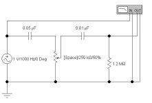
I think C1 is an insurance policy to protect from DC on other equipment, but I am wondering what C2 is doing? A passive low pass filter?
There are a lot of feedback circuits there, would be interesting to hear more from the experts how they are all contributing. I see cathode of the phase splitter to the cathode of the driver, the usual negative feedback from the OPT secondary to the cathode of the driver, but then there is something going on from the UL tap to the negative FB connection?
Is this really a thing? The tube has a specification for the maximum colde voltage, so as long as that is not exceeded how does having higher B+ on the anode affect the tube if it is not conducting? I can understand a soft start solution where extreme molly-coddling is required of a valuable and hard-to-replace tube, but in this case the tube is being used in the way it was designed for.Even more useful would be soft-start. This would allow the EL84 filaments to warm before being hit with straight B+. Extending Tube Life
Even more useful would be soft-start. This would allow the EL84 filaments to warm before being hit with straight B+. Extending Tube Life.
Is this really a thing?
This topic has been the subject of "heated" debate for decades (pun intended)! 🙂 I don't know enough to make a decision either way. My Dynaco ST-70 series ii (Panor Corp 1992) doesn't have it, and I haven't had any issues since I bought it new in 1992. I replace the output tubes about every 3,000 hours anyway, so maybe I never would notice any difference. EL34 and EL84 tubes are "expensive" but not a total budget buster so I just replace them on a regular basis. It's still possible to get four 6P14P-EV or 6P14P-ER tubes for less than a hundred bucks from overseas.
Last edited:
R4/C3 is a positive feedback that increases the amplification a bit.What is the function of R4 and C3? See schematic in post #1.
Same design as used in SCA35
C1 should always be installed, altho we see many examples on DIY where they are not.My first technical question is, with modern equipment, C1 is no longer necessary, correct?
Some people install a 2-stage HP filter on a power amp front end to prevent LF transients from entering their amp at all.
This provides Loud Speaker protection. And LF IMD prevention.
A Current Limiting (CL) resister is a worthwhile addition to the AC line in. As well as limiting the inrush it will somewhat delay the B+.
Why substitute a #14 Power Cord for the #18 provided? The current requirements of this amp are minimal.
Does anyone ever take the time to measure or calculate the resistances involved?
From first principles & the AWG wire tables the resistance of 1000 ft #10 copper wire is One Ohm. Easy to remember, look it up.
A 10 ft power cord would have 20 ft of conductor exclusive of the Neutral. So 20 ft of #10 would be 0.02R
The resistance doubles every 3 wire sizes. So up six wire sizes to #16 we have 0.08R in the pwr cord.
Another two sizes to #18 we are now at 0.128R in the 10 ft pwr cord. No special instruments or calculators required.
Very useful to know for a tech or engineer working in the field.
There are still four contacts in that path. But they are there whatever pwr cord is used.
And for the more curious not difficult to measure. With simple equipment by the 4-wire method. 👍
Attachments

Why substitute a #14 Power Cord for the #18 provided? The current requirements of this amp are minimal.
Does anyone ever take the time to measure or calculate the resistances involved?
From first principles & the AWG wire tables the resistance of 1000 ft #10 copper wire is One Ohm. Easy to remember, look it up.
A 10 ft power cord would have 20 ft of conductor exclusive of the Neutral. So 20 ft of #10 would be 0.02R
The resistance doubles every 3 wire sizes. So up six wire sizes to #16 we have 0.08R in the pwr cord.
Another two sizes to #18 we are now at 0.128R in the 10 ft pwr cord. No special instruments or calculators required.
Very useful to know for a tech or engineer working in the field.
There are still four contacts in that path. But they are there whatever pwr cord is used.
And for the more curious not difficult to measure. With simple equipment by the 4-wire method.
Because decades of listening and experimentation prove that not everything can be measured in terms of resistance. I could use cheap, thin zip cord for speaker wire, but I don't. I could use 99 cent RCA cables throughout, but I don't. Wire is just wire, right?
Very useful to know for a tech or engineer working in the field.
Maybe, but that's not the environment where audiophiles are.
Does anyone ever take the time to measure or calculate the resistances involved?
Do you ever take decades to experiment and listen to the effects of changes?
Thanks, but we really don't need to go here again ... ever.
Last edited:
All BS. Why are you here on DIY asking for advice from others with experience? Do you want the real deal or the dreamer edition?
Have you ever designed & built an audio amplifier from the ground up, not from a kit?
Or any other kind of amplifier? I've done that about 50 times & only once from a kit. You can read me in Glass Audio & AudioXpress.
And many other pieces of electronics's. I speak from long experience & the comments of those who used the amps & other equipment.
But audio was never my day job. Nor was being an AudioPhool. If it can't be measured it is probably not real. 😆
Attachments
I bought this-Does anyone make a kit that would fit inside the tiny ST-35 chassis? It's not too late to plan for that if someone offers an ultra-compact kit.
https://www.ebay.com/itm/124204143122?
Working on completing circuit that uses it. I changed 10 uf timing electrolytic to 22uf for more than 5 seconds delay. Didn't want the 1 minute version cuz I thought resolution of the single turn pot would be poor.
Jim
ps. heres another that may be better, but larger. iirc- one I ordered is approx 3/4" x 3" long
https://www.ebay.com/itm/284398492288?
Last edited:
The days of "just replacing them" from "overseas" suppliers is very much over. I'm not sure if you got the memo. The last production runs of tubes out of Russia and China from a decade ago are very much "The Final Episode" to this story. If you haven't thought things through - we are now in preservation and conservation mode. We just exited the Golden Age of tube audio - that largely peaked in the 1990s and filtered down to the ordinary people in the 2000s and 2010s. Whatever you have Built or Designed through DIY sweat equity is as good as it's going to get! Finalize the cosmetics of your projects. If your design is meritworthy enough - acquire and preserve a small cache of replacement parts that you can eventually bequeath to someone curator custodian in the future decade or two when you get too old to care about audio, or are forced to move, or die of a ripe old age. Someone might want the pieces and parts to go with them as a working historical testimony.This topic has been the subject of "heated" debate for decades (pun intended)! 🙂 I don't know enough to make a decision either way. My Dynaco ST-70 series ii (Panor Corp 1992) doesn't have it, and I haven't had any issues since I bought it new in 1992. I replace the output tubes about every 3,000 hours anyway, so maybe I never would notice any difference. EL34 and EL84 tubes are "expensive" but not a total budget buster so I just replace them on a regular basis. It's still possible to get four 6P14P-EV or 6P14P-ER tubes for less than a hundred bucks from overseas.
That said, taking every measure to Preserve and Conserve (such as current limiters and B+ delays) is prudent at this point.
JJ is in active production of tubes including EL34. Some russian tubes are smuggled in spite of sanctions, some chinese tubes are in active production. So, there is no shortage yet!The last production runs of tubes out of Russia and China
+1JJ is in active production of tubes including EL34. Some russian tubes are smuggled in spite of sanctions, some chinese tubes are in active production. So, there is no shortage yet!
The prices have increased but the volume is still there for the current references both in power and in signal.
On the other hand it is clear that the resource is not unlimited (I speak for Russian tubes) for the Chinese, as long as there is a market...
and for the others (JJ, EH etc etc) well it's the same, as long as there is a market...
This project started Jan 26/23 in yet another thread.
Since then lots of talk but little action. When will the soldering iron be plugged in? 😀
Since then lots of talk but little action. When will the soldering iron be plugged in? 😀
The days of "just replacing them" from "overseas" suppliers is very much over.
Not quite yet. I thought that 20 years ago, but common tubes are still in production, and I have ordered NOS tubes from Ukraine successfully three times recently. China's current tube production is improving in quality and expanding to other tube types, but it still leaves much to be desired as far as quality control. Demand for new tubes within China and Japan apparently is high enough on its own to sustain new manufacturing, and Ukraine, Kazakhstan, and others are still shipping NOS tubes. Tubes from Russia seem to be sold in bulk to other countries and then resold globally. Since these tubes also are common in guitar amplifiers, that drastically increases demand, and where there is a demand, supply usually follows. It's not just demand from audiophiles, the guitar folks love tubes too.
I don't have any way to estimate how many millions of new old stock Soviet-era 6P14P-EV and 6P14P-ER tubes remain, but there is plenty of time to buy enough replacement sets to last for the rest of my lifetime. If I end up liking this amplifier, I'll put a supply of them on my shelf and never worry about it again. I'm pretty sure they won't go down in value over time should I ever want to sell them. The other amplifier that I am using is the little Huaji Audio Chinese kit amp that I built, which can use ordinary Chinese 6P14 or Russian 6P14P tubes, not the special Soviet military variants, since it doesn't run the tubes as hard. Huaji Audio kit build I have bought enough 6N1P-EV driver tubes for it to last the rest of my lifetime, and both amplifiers can use the 6P14P-EV and 6P14P-ER tubes, so I'm all set there.
For anyone interested specifically in ST-35 tube life and ways to (possibly) extend it in this amplifier, that topic is in the pre-build thread devoted to the power supply and tube life, before I decided whether or not to buy the kit. Based on the lengthy discussion there, I have decided to leave the voltages as they are, at least for now.
This project started Jan 26/23
This project actually started 5/26/2023.
If it can't be measured it is probably not real
Good luck with that. Feel free to ignore this thread.

The tube has a specification for the maximum cold voltage, so as long as that is not exceeded how does having higher B+ on the anode affect the tube if it is not conducting? I can understand a soft start solution where extreme molly-coddling is required of a valuable and hard-to-replace tube, but in this case the tube is being used in the way it was designed for.
OldHector, I have the same question about delayed turn on circuits. The debate has been going on for so long that I don't expect to ever see a definitive answer with test results and proof of whether it makes a substantial difference and if so how much difference. My Dynaco ST-70 series ii doesn't have delayed turn on (I thought about adding it), and it doesn't have a thermistor either. I have had no problems after 30 years of use, with 20 of those years being daily use 8 hours per day or more 365 days per year. I'll put a thermistor in the ST-35 just in case.
Bob Latino weighed in on this issue in the ST-35 at one point:
The other thing to consider is that who knows how many thousands of Dynaco ST-35 and Dynaco SCA-35 tube amps are still in use after 40 + years in service? Both amps had solid state rectifiers with NO DELAY. Many of these amps are still out there in service and still working fine after 40+ years of no delay - SO - (IMHO) the "danger" of using a solid state rectifier with no delay and the idea of cathode stripping and shorter output tube life on amps like this may be exaggerated ...
Bob
Source
Sweetwater says this:
Many tube experts doubt whether cathode stripping is even possible or ever occurs. Others believe that it can only happen with directly heated tubes. Still others believe that cathode stripping only happens at high voltages (typically above 10 kilovolts).
Source
Another view:
So in summary it seems that:
- valves are not damaged by HT when cold
- but heated with no cathode current they will slowly lose emission
Source
A whole thread on the topic: https://www.diyaudio.com/community/threads/doubts-on-cathode-stripping-in-tubes.79405/page-2
Last edited:
- Home
- Amplifiers
- Tubes / Valves
- New DynaKitParts ST-35 Build