Hi, I have now installed the Hiraga pcb with Kobuta reg. I adjusted the reg voltage to 22Vdc. The card gets 26Vdc from PS.
Then adjusted the dc offset to +- 0,000Vdc.
The Hiraga drives the mid / tweeter ( DPA 6.1 for the bass ).
All look good, connect signal and speaker cables.
Put on a cd, there is sound ( :
It sound realy good, very relaxed. Maybe have to turn the pot up a click or two to same level as before.
But then I notice after 30 min, it dont get hot. not even litle hot. Is maybe the output transistors damage? From to much heat when desoldier from old pcb. Or would I then not get any sound if damage? Frank

Good evening, I have got my friend messure how many watt the amp draw. Only 29W, the amp with the old card draw 300w.
This amp can not play in class A? 400mv give 1.2A, and dont get hotter then body temp. What do you think?
Frank
This amp can not play in class A? 400mv give 1.2A, and dont get hotter then body temp. What do you think?
Frank
My guess is that the current sources (Q9,Q14) need to be adjusted to set the bias. You could replace them with the original resistor values (47k) to see if this will change things...
I will check that out. But with 1.2A it sould go in Class A and consume moore wattage.
The old 8W Hiraga consume 90W at idle. Something is wrong here.
Frank
The old 8W Hiraga consume 90W at idle. Something is wrong here.
Frank
The transistors ( 2SC5200 / 2SA1943 ) are on the heatsing. And the heatsink are huge.
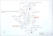
Colore on diode was red, change to white.
Colore on diode was red, change to white.
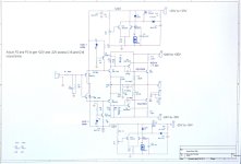
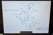
Remove R9 and R10, replace those with 2K trimmers as adjustable resistor and try to set up 1.4K or so before you soldered into your PCB. Adjust (keep decreasing it both) it until you get the required bias current and close to 0V on the speakers terminal. After set up remove those and replace it with close value resistors or leave it like that.
What are the voltages across R9 and across R10?
With trimmers differences can occur (that will change the open loop gain for both halves and the feedback has to take care of that... too).
This will also set the idle currents for Q5/Q6 and Q7/Q8. Make sure the voltages across R13 and R14 are equal, even if this sets the output offset away from zero Volts (that's what P1 is used for).
Repeated: Q5/Q6 should NOT be mounted on the same heat sink as for Q7/Q8.
That counts for Sziklai's in general due to thermal runaway risk.
I think the regs only adjust dc on output I think R9 R10 are the ones . It is this one? As I remember I found the correct value by inserting trimmers, adjusted to correct, took trimmers out and substituted them with resistor

"I think the regs only adjust dc on output."
If you mean the DC voltage regulator circuit's, they're for the supply voltage of +/-22Vdc only, not for the DC-offset on the output of the amplifier.
Make sure these regulators provide a symmetrical +/-22Vdc supply for the amp.
"I think R9 R10 are the ones."
About what?
"It is this one?"
Which one (-'s)?
"As I remember I found the correct value by inserting trimmers, adjusted to correct, took trimmers out and substituted them with resistor."
You mentioned this, but are these resistors of the same value? In the circuit 1k5//3k0 are shown.
Q5/Q6 are on the little 'bend-fingers' heat sinks (separate from each other, I hope) on the pcb, so that's ok.
The heatsinks for Q7/Q8 are not 'huge'. They're small actually.
Oh no, you've used utp-cable wires as hookup wires... they're not made for this purpose (they break).
Better replace them with decent wires.
AFC, you're right: +/-22Vdc for pre, +/- 24-35 for main.
I'm a bit used to the original design, and not this pre-reg variation.
I'm a bit used to the original design, and not this pre-reg variation.
Mine plays nicely, I believe bias is around 1.2 1.5 amp . 5 kilo heatsink for each side is about 50 degrees Celsius.
I like the idea of clean stable dc for input transistors instead of a crude resistor, the high bias forces the power supply to produce some ripple, we don't want ripple on input transistors
I like the idea of clean stable dc for input transistors instead of a crude resistor, the high bias forces the power supply to produce some ripple, we don't want ripple on input transistors
- Home
- Amplifiers
- Solid State
- Start up Hiraga 30W w/Kobuta reg