I´ve got a Hifonics BXi 8000D here, it breaks way before reaching it´s rated power.
I measured these waveforms at the output section of every bank, there is only one FDA59N30 per bank in at the moment.
Railvoltage reaches +/- 124V
The amplifier builds up heat, as it goes, without any load.
So my question is if these waveforms are fine?
I measured these waveforms at the output section of every bank, there is only one FDA59N30 per bank in at the moment.
Railvoltage reaches +/- 124V
The amplifier builds up heat, as it goes, without any load.
So my question is if these waveforms are fine?
Attachments
-
 IRF1 Gate 1µS.png10.4 KB · Views: 100
 -
 IRF10 Rechts Minus ZWK.png8 KB · Views: 95
 -
 IRF10 Mitte Rechteck 5µS.png11.4 KB · Views: 97
 -
 IRF10 Mitte Rechteck 1µS.png9 KB · Views: 92
 -
 IRF10 Gate Takt.png10.6 KB · Views: 91
 -
 IRF9 Source 5µS.png13 KB · Views: 92
 -
 IRF9 Source 1µS.png9 KB · Views: 85
 -
 IRF9 Mitte ZWK Plus.png8.1 KB · Views: 94
 -
 IRF9 Gate 5µS.png11.6 KB · Views: 92
 -
 IRF9 Gate 1µS.png9.1 KB · Views: 81
 -
 IRF1 Gate 5µS.png11.7 KB · Views: 88
 -
 IRF1 Mitte ZWK Plus.png8.1 KB · Views: 103
 -
 IRF1 Source 1µS.png10.3 KB · Views: 81
 -
 IRF1 Source 5µS.png12.9 KB · Views: 91
 -
 IRF2 Gate Takt (2).png10.5 KB · Views: 90
 -
 IRF2 Mitte Rechteck.png10.8 KB · Views: 88
 -
 IRF2 Rechts Minus ZWK.png8 KB · Views: 84
I don´t know how to use my scope in differential mode, isn´t that more of a probe thing? I will read up on that topic.
They are heating at the same rate, the thermal camera didn´t show any color difference between them.
They are heating at the same rate, the thermal camera didn´t show any color difference between them.
A differential input uses two inputs to produce a single waveform. The simplest way to get a differential input is to use a differential probe. A differential probe has two signal leads and a mixer amplifier built into it. It feeds the scope a normal signal (a composite of the two signals input into the differential probe). The problem with differential probes is that they're expensive.
The alternative is to use two scope probes and and both inputs of your oscilloscope. This is how you have to set up your scope:
Two probes
Both scope inputs used
Input set to add
Both channels set to DC coupling
Both channels set to 'cal'.
Both vertical amps set to the same voltage
Ch2 input set to invert
Bandwidth limited (works best for most measurements in car amps)
Trace aligned to the reference line on the scope's display
Ground leads for both probes connected together (not always necessary)
After setting up the scope, you need to confirm that it's working as it should. With the vertical amp set to 5v/div, touching the probe that's connected to Ch1 to the positive terminal of your 12v power supply should make the trace deflect about 2.5 divisions up from the reference (like it always does, seen below). Doing the same with the probe connected to Ch2 should make the trace deflect down about 2.5 divisions. Touching both probes to the positive terminal of the 12v power supply should cause no deflection. If it does, something isn't right.
I know that this may not be as simple as the isolated scope but if you take the time to learn it one time (even if it takes an hour or more of your time), you have that knowledge and this tool to use for the rest of the time you need to use a scope. Using the analog scope will give you much larger and cleaner waveforms.
Sorry for the late reply.
I can display the Source just like you described, I´m using a Hameg HM1505 analog scope for now.
What is the next step and what is the advantage of measuring that way in this scenario?
I can display the Source just like you described, I´m using a Hameg HM1505 analog scope for now.
What is the next step and what is the advantage of measuring that way in this scenario?
So which points should I measure now?
The deadtime for the IRS21844S is set with a 10kOhm resistor at both drivers.
What other reasons could there be for excessive heat?
The deadtime for the IRS21844S is set with a 10kOhm resistor at both drivers.
What other reasons could there be for excessive heat?
There could be multiple reasons. Having only one FET per bank causes a problem in some amps.
I need to see the gate drive for each installed FET. In differential mode, the ch1 probe will be on the gate. The channel 2 probe will be on the FET source. There will be no scope ground connection to any of the FETs but the scope should be grounded to the 12v power supply ground terminal (as always).
I need to see the gate drive for each installed FET. In differential mode, the ch1 probe will be on the gate. The channel 2 probe will be on the FET source. There will be no scope ground connection to any of the FETs but the scope should be grounded to the 12v power supply ground terminal (as always).
Yes. The scope will display the difference between the two probes, not the signal referenced to ground. You can post one waveform for a single FET to make sure that you have everything set up right, unless you're sure you do have it set up right.
The bottom fets are getting hotter to the touch.
Attachments
-
 CF642EF4-F56F-490C-B41B-2CD6F7852887.jpeg392.9 KB · Views: 68
 -
 D9EB5D61-D2F4-4BE1-AB38-23BD348947EC.jpeg421.9 KB · Views: 69
 -
 25A3DEDB-A55D-4833-B930-26B7D23B69F0.jpeg661.7 KB · Views: 83
 -
 64FCD305-DA45-47DE-B60B-AB4091EAF9D9.jpeg398.6 KB · Views: 65
 -
 8C4ADC11-6EC3-4CE8-9007-A7918AFC12E8.jpeg401.7 KB · Views: 60
 -
 DC070E3A-117B-4BEB-8B1A-C565363CCCC0.jpeg391.5 KB · Views: 65
The first picture has the top row fet´s this waveform seems ok, the rest is the bottom row. This seems kinda distorted and not very defined.
I used a 10:1 probe.
I used a 10:1 probe.
If you touch both probes (in differential mode) to the drain of one of the PS FETs, do you get a straight line at 0v (no deflection from the reference line)?
OK. I just wanted to make sure that the setup was working as expected.
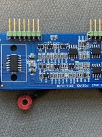
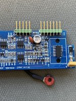
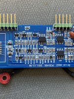
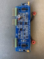
Post photos of the audio driver board and any drivers in the audio circuit.
Post photos of the audio driver board and any drivers in the audio circuit.
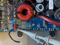
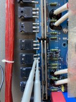
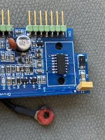
Some photos of the driverboard, the board uses the IRS21844S.
Attachments
-
 9A3EA202-F8EB-4498-B1A7-12F093A3A7A2.jpeg685.2 KB · Views: 82
 -
 C4D94423-08A9-40E5-8C83-59E7E496BE45.jpeg685.7 KB · Views: 80
 -
 D363C208-6BFD-4C96-954C-49800ECAF34D.jpeg698.2 KB · Views: 68
 -
 0B699A25-0020-4D36-B47B-FC5B41DE6FD2.jpeg874.4 KB · Views: 72
 -
 DC47EFA3-43C3-4078-AB31-AC7FCD146597.jpeg629.2 KB · Views: 66
Did you replace these when the output transistors failed?
Are there any driver transistors or driver ICs between the driver board and the output transistors?
Do you have 12v (referenced to the negative rail) on pin 7 of the 21844?
Are there any driver transistors or driver ICs between the driver board and the output transistors?
Do you have 12v (referenced to the negative rail) on pin 7 of the 21844?
The IRS21844S got replaced.
There are no driver transistors as I can see, the 21844 is driving the Output-Fet´s directly.
I have 11,85V referenced to the negative rail.
There are no driver transistors as I can see, the 21844 is driving the Output-Fet´s directly.
I have 11,85V referenced to the negative rail.
Is that board in a socket or is it a board that was never used?
Check the output of each IC drive section. Which have good drive signals? Ch2 probe on com/vs ch1 probe on lo/ho.
Check the output of each IC drive section. Which have good drive signals? Ch2 probe on com/vs ch1 probe on lo/ho.
I used new pins for this board.
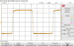
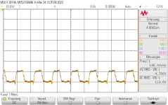
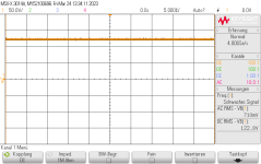
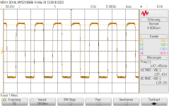
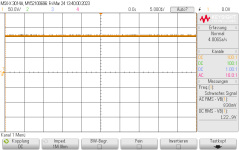
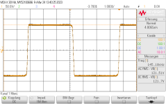
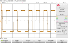
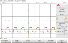
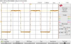
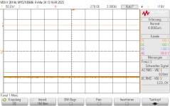
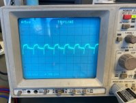
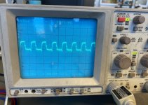
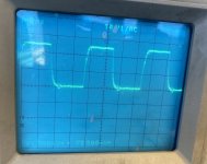
First is the Waveform at Pin 1 of the 21844‘s
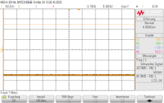
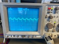
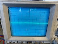
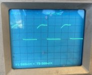
Pic 2 is the low side drive
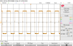
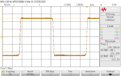
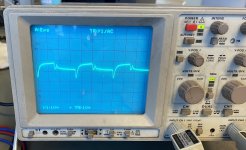
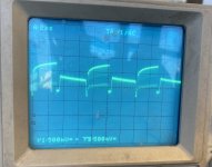
Pic 3 and 4 is the high side drive
High side drive should be a somewhat clean Square wave too?
First is the Waveform at Pin 1 of the 21844‘s
Pic 2 is the low side drive
Pic 3 and 4 is the high side drive
High side drive should be a somewhat clean Square wave too?
Attachments

- Home
- General Interest
- Car Audio
- Hifonics BXi 8000D - good waveforms?