I would like to share with you the result of my new hybrid amplifier.
The my first version of this my amplifier was made in 2010 then i made some improvements.
The new version uses a very simple and cheap tube driver with 6Z51P or D3a that can deliver 40Vrms with a single tube.
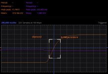
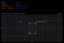
The distortion is about 1.5% at 33Vrms so about 150W on 8ohm.
This project collects all the experiences made in these years then it born with all these characteristics:
This configuration has been analyzed very well in the article Bulding better buffer on Electronics World november 1992.
The same design as been used in many Audio Research amplifiers like the Audio Reasearch D100 and the D400.
Also the Pioneer A-09 and the M-6 use a Diamond Buffer on output stage but these implement dynamic current generators with some stability problems.
Advantages of this type of configuration compared to a conventional:
● compensation of Vbe non-linearities between driver and final so very low distortion without feedback
● high slew-rate and large frequency band
● temperature run-away compensation without sensors if driver and final transistors share the same heatsink
● high input impedance if driver stage use current generator (I1 & I2) auto protected by short circuit on output
Disadvantages of this type of configuration compared to a conventional:
● the bias current in the driver limits the current supplied to the load
It is evident that there are many benefits, but to overcome the problem of the current supplied to the load you need to study well the working points of the driver and final.
All the pcb will be available at low cost on Ebay shop or you can download the Eagle files to produce these in your local area
I don't get money from this Ebay shop.
The my first version of this my amplifier was made in 2010 then i made some improvements.
The new version uses a very simple and cheap tube driver with 6Z51P or D3a that can deliver 40Vrms with a single tube.
The distortion is about 1.5% at 33Vrms so about 150W on 8ohm.
This project collects all the experiences made in these years then it born with all these characteristics:
- no global feedback design
- passive components without any compromise on any section
- only few parts on the signal path, only 3/4 active components
- very short signal path
- very low output impedance (near to 0.1ohm) for high damping factor (near to 80)
- very high output current, output devices able to manage 60A
- high output power to drive any loudspeakers including ESL, 140W on 8ohm and ?W on 4ohm
- very good slew-rate
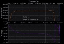
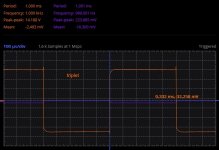
- large frequency band, near to 1.5MHz for the IRF820 configuration
- high separation from power supply for all the sections
- power supply separated for each channel
- zero noise
- ultra low distortion in the current amplifier
- zero dc offset, dc servo loop
- no fuse on the signal path
- no relay on the output signal
- only a single vacuum tube for the voltage amplifier
- only one interstage capacitor on the signal path
- high input impedance 110Kohm
- high voltage gain able to be driven directly by any source
- voltage stage and driver stage working in pure class A operation
- high efficiency near to class AB
- compact chassie
This configuration has been analyzed very well in the article Bulding better buffer on Electronics World november 1992.
The same design as been used in many Audio Research amplifiers like the Audio Reasearch D100 and the D400.
Also the Pioneer A-09 and the M-6 use a Diamond Buffer on output stage but these implement dynamic current generators with some stability problems.
Advantages of this type of configuration compared to a conventional:
● compensation of Vbe non-linearities between driver and final so very low distortion without feedback
● high slew-rate and large frequency band
● temperature run-away compensation without sensors if driver and final transistors share the same heatsink
● high input impedance if driver stage use current generator (I1 & I2) auto protected by short circuit on output
Disadvantages of this type of configuration compared to a conventional:
● the bias current in the driver limits the current supplied to the load
It is evident that there are many benefits, but to overcome the problem of the current supplied to the load you need to study well the working points of the driver and final.
All the pcb will be available at low cost on Ebay shop or you can download the Eagle files to produce these in your local area
I don't get money from this Ebay shop.
Attachments
-
 Sch2022b.gif20.5 KB · Views: 1,775
 -
 Ibridone_2022_ph3.jpg160.2 KB · Views: 1,749
 -
 Ibridone_2022_ph2.jpg164.6 KB · Views: 1,536
 -
 driver_sch2022a.jpg39.7 KB · Views: 1,836
 -
 driver_sch2022.jpg82 KB · Views: 2,388
 -
 Ibridone2022_sch.jpg160.5 KB · Views: 2,384
 -
 Ibridone_2022_freq_8ohm.jpg70.4 KB · Views: 2,074
 -
 Ibridone_2022_thd1_8ohm.jpg51.4 KB · Views: 1,603

First listed characteristic.... Using a tube works against this, but there maybe a reason I am not aware of?...
What would you suggest as a better option?no global feedback design
N0 he doesn´t 🙂Can you tell why you used a tube as preamp? Your list of requirements has things like low distortion, short signal path etc, showing you want a clean and low noise design with very low nolinearity.
Using a tube works against this, but there maybe a reason I am not aware of?
Jan
That applies only to the unity gain/current amplifier/buffer stage , which is required to perfectly deliver all the distortion (sorry, "generated harmonics" 🙄 generated by the tube, into the speaker.
The design boasts of 1.5% distortion.
Mentioning "Class A gain and driver stages" is irrelevant and misleading, amplifier Class is defined by final stage bias and conduction angle.
Some of the "features" are just design choices, such as no fuses, no relays, etc., do not specially apply to any design, including hybrids.
"Zero noise" is quite optimistic in my view 🙂
As of the OP, I CONGRATULATE him for actually designing and building it, instead of subjecting us to just another simulation 🙂
Talk is cheap, I much appreciate somebody who actually rolls up his sleeve and does something.
As in using wire, components, soldering iron, etc. 🙂 👍
Member
Joined 2009
Paid Member
Here the files for the simulations with LTspice
Download triode.asy from Ducan's Amp Pages.
Add these following ines in the file C:\Program Files\LTC\lib\cmp\standard.bjt or in C:\Users\[Windows user]\Documents\LTspiceXVII\lib\cmp\standard.bjt to have the transistors models:
.MODEL Qnjw0302g pnp IS=5.16751e-16 BF=114.657 NF=0.895716 VAF=50.2189 IKF=6.409 ISE=3.9641e-15 NE=4 BR=1.47167 NR=0.923324 VAR=255.567 IKR=6.34299 ISC=3.96408e-15 NC=2.82194 RB=2.66347 IRB=0.1 RBM=2.0828 RE=0.0001 RC=0.0652395 XTB=1.45322 XTI=1.08126 EG=1.05 CJE=2.14504e-09 VJE=0.4 MJE=0.376227 TF=2.16864e-09 XTF=1000 VTF=843.737 ITF=501.348 CJC=5e-10 VJC=0.95 MJC=0.251547 XCJC=1 FC=0.8 CJS=0 VJS=0.75 MJS=0.5 TR=1e-07 PTF=0 KF=0 AF=1
.MODEL Qnjw0281g npn IS=4.36849e-12 BF=98.1488 NF=1.01332 VAF=37.9046 IKF=9.71849 ISE=1e-16 NE=1.8326 BR=0.79921 NR=1.09994 VAR=339.743 IKR=5.77305 ISC=1e-16 NC=2.71592 RB=2.74892 IRB=0.33289 RBM=2.74892 RE=0.000344671 RC=0.03203 XTB=1.7742 XTI=1.12262 EG=1.20598 CJE=3.66793e-09 VJE=0.74806 MJE=0.85 TF=2.27115e-09 XTF=1000 VTF=912.955 ITF=296.602 CJC=5e-10 VJC=0.95 MJC=0.270858 XCJC=0.98254 FC=0.8 CJS=0 VJS=0.75 MJS=0.5 TR=1e-07 PTF=0 KF=0 AF=1
.MODEL Qmje15032 npn IS=3.7344e-10 BF=86.8313 NF=1.23974 VAF=31.5491 IKF=9.1678 ISE=9.2499e-12 NE=3.28127 BR=5.59346 NR=1.33161 VAR=2.1791 IKR=5.15023 ISC=4e-13 NC=4 RB=9.54492 IRB=0.1 RBM=0.1 RE=0.000568481 RC=0.0931741 XTB=0.737036 XTI=1.04983 EG=1.206 CJE=3.05969e-09 VJE=0.648491 MJE=0.352663 TF=4.94819e-09 XTF=1.50001 VTF=1.0001 ITF=0.999982 CJC=3.00108e-10 VJC=0.600021 MJC=0.40991 XCJC=0.8 FC=0.534651 CJS=0 VJS=0.75 MJS=0.5 TR=1e-07 PTF=0 KF=0 AF=1
.MODEL Qmje15033 pnp IS=7.51228e-10 BF=134.35 NF=1.25737 VAF=12.5778 IKF=1.88497 ISE=7.74267e-12 NE=3.34528 BR=5.14173 NR=1.47488 VAR=1.4505 IKR=7.47186 ISC=3.25e-13 NC=4 RB=4.37743 IRB=0.1 RBM=0.1 RE=0.000332989 RC=0.381218 XTB=0.223027 XTI=1 EG=1.05 CJE=3.06005e-09 VJE=0.64838 MJE=0.352991 TF=4.78203e-09 XTF=1.50001 VTF=1.00006 ITF=0.999988 CJC=3.00101e-10 VJC=0.600019 MJC=0.409916 XCJC=0.8 FC=0.534975 CJS=0 VJS=0.75 MJS=0.5 TR=1e-07 PTF=0 KF=0 AF=1
Attachments
Last edited:
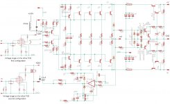
There is no trimmer for adjusting the bias so you must use exactly the transistors described in the project.
To use other types you need to make many test and in some case set R9-R12 to 1ohm or more.
This current amplifier have an input impedance near to 20Kohm and it absorbs a max peak current of 2mA also when it drive 2 ohm load at the max output level (simulated with 40Vrms on 2ohm load so 20A).
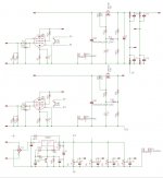
I have add a power supply regulator to eliminate any ripple coming from main capacitors after the diode bridge and it allow a soft start with these advantages:
The op-amp in the circuit is a DC servo to eliminate DC offset and it work in very low frequency band.
I will publish soon the complete list of components and more photos.
To use other types you need to make many test and in some case set R9-R12 to 1ohm or more.
This current amplifier have an input impedance near to 20Kohm and it absorbs a max peak current of 2mA also when it drive 2 ohm load at the max output level (simulated with 40Vrms on 2ohm load so 20A).
I have add a power supply regulator to eliminate any ripple coming from main capacitors after the diode bridge and it allow a soft start with these advantages:
- the capacitors near the output transistors are charged slowly so the fuse inserted before does not blow
- after switch-on the output stage should start without dc offset and it will wait the vacuum tube warm up
The op-amp in the circuit is a DC servo to eliminate DC offset and it work in very low frequency band.
I will publish soon the complete list of components and more photos.
I have published this project also in the Solid state section because in the Tubes / Valve section there is no interest probably because there are only pure tube lover who like to hear amps with Zout > 2 ohms 🙂
I think that the Hybrid amp. get the best from both technologies, since the 1999 I abandoned the pure tube amplifiers and I started to get interested in this type of amplifiers starting from my workhorse, the Power Follower.
Here the pcb files, one still to verify.
I think that the Hybrid amp. get the best from both technologies, since the 1999 I abandoned the pure tube amplifiers and I started to get interested in this type of amplifiers starting from my workhorse, the Power Follower.
Here the pcb files, one still to verify.
Attachments
I suggest you to forget the 6922/ECCC88/E88CC/12AX7/12AU7/12AY7 and test the pentode in triode connection, another life.I did similar. 6922 > volume/ loudness > 6922 > tone stack > 0.0007 Thd mosfet amp.
Not sure it hits 1.5mhz 20A max
110db s/n at 1 watt.
Sounds fantastic
See these cheap pentode tested on Bartola® article.
segmented ESLs ? diy panels ?Hi Andrea, I think this amplifier might make my segmented ESLs happy ?.
No! Daan, you too?? I always thought you were so mature ...Maybe Andrea listens with his ears instead of his oscilloscope;
Jan
Switching power supply sound like the conventional probably because the regulator separate the amplifier from power supply.
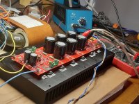
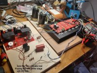
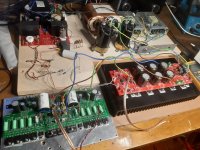
I am creating a new test to compare this power diamond buffer to normal triplet Darlington.
I am creating a new test to compare this power diamond buffer to normal triplet Darlington.
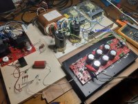
Here the new test environment to compare triplet darlington to diamond buffer.
I borrowed an already built module of triplet darlington from a friend of mine.
It is useless to measure the distortion because both have much lower values than the tube voltage amplifier.
I have used for both the same interstage capacitor Audyn-Cap Plus, this is worse than the Jantzen Superior Z-Cap.
Attachments


- Home
- Amplifiers
- Solid State
- High Power Hybrid Amplifier