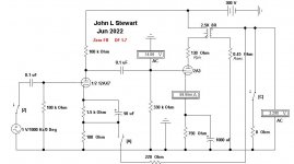
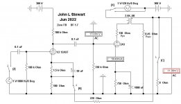
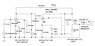
This simple amp, a 2A3 driven by half of a 12AX7 is connected with Schade FB & compared to if it were
connected with the same degree of NFB from OPT secondary to the AX7 cathode. And without FB at all.
With no FB the Damping Factor (DF) is 1,7. With 9.4 db Schade FB connected the DF improves to 3.4.
But with the full loop FB of 9.8 db the DF becomes 11.74.
Schade NFB does not correct for OPT winding resistance.
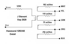
The winding resistances used here are similar to that of a Hammond 125DSE.
connected with the same degree of NFB from OPT secondary to the AX7 cathode. And without FB at all.
With no FB the Damping Factor (DF) is 1,7. With 9.4 db Schade FB connected the DF improves to 3.4.
But with the full loop FB of 9.8 db the DF becomes 11.74.
Schade NFB does not correct for OPT winding resistance.
The winding resistances used here are similar to that of a Hammond 125DSE.
Attachments

My dim understanding of the best way to implement plate-grid feedback around an output stage is that you need the very high plate resistance and gain of a pentode for the driver tube and you want the higher gain of a pentode for the output stage. My understanding is that the idea is to get the output power of a pentode but without the phase shifts of the OPT inside the feedback loop.
What happens if you conduct the same experiment using something like a 6AC7 driving a 6L6, comparing 'Schade' NFB to global NFB?
What happens if you conduct the same experiment using something like a 6AC7 driving a 6L6, comparing 'Schade' NFB to global NFB?
What Schade FB Leaves Behind....................................And Brings With It.
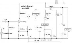
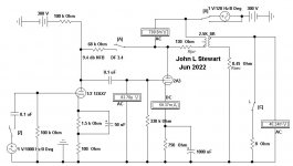
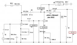
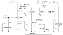
In these sims a One Volt 'Interfering' signal has bee inserted into the 300V PS lead, That would be PS Hum.
The driver has its own PS so that it is isolated from the hum. How much hum gets thru to the speaker terminals?
The switch 'X' allows the hum to be added into the output tube plate supply.
Without FB both Amps put ~40 mV at the speaker terminals.
But when Schade FB is applied the hum increases to ~46 mV.
In the FB Pair the hum at the speaker terminals is reduced to ~11 mV.
The DC resistances of a Hammond 125DSE are in the other
Measured using a constant current source applied to the ends of the windings.
Attachments
-
 2A3 12AX7 9.4 db Schade FB PS Hum No FB.JPG40.8 KB · Views: 144
 -
 2A3 12AX7 9.4 db Schade FB PS Hum with FB.JPG42.6 KB · Views: 146
 -
 2A3 12AX7 FB Pair 9.8 db NFB PS Hum with FB.JPG42.8 KB · Views: 131
 -
 Hammond 125DSE Detail.JPG20.1 KB · Views: 125
 -
 2A3 12AX7 FB Pair 9.8 db NFB PS Hum No FB.JPG41.1 KB · Views: 159
What happens if you conduct the same experiment using something like a 6AC7 driving a 6L6, comparing 'Schade' NFB to global NFB?
---------------------
Pentodes are a better way to go altho here on DIY many are allergic to them.
The bottom line for Schade is the same but in different ways.
Rain here tomorrow, I'll stick something together with the toobz you suggest.
All this really begs the question, 'Why would we use Schade' when the other way is so much better. 🙂
It allows a floating output winding without added cost or complication.'Why would we use Schade' when the other way is so much better.
It can avoid the need to figure OT polarity (which comes out wrong fully 50% of the time)
It allows us to self-delude "That's not overall NFB!"
Feedback from the OPT primary also reduces distortion in the OPT, and improves its bandwidth. That part is great; it's the bit about loading the driver valve that isn't so great. One option is to bring the feedback a little further back to the cathode of the driver valve. DC is involved, so that cathode resistor needs adjusting, so an iterative approach works. Or could be calculated, but bulky.
All good fortune,
Chris
All good fortune,
Chris
In my current experimental transmitter triode SE amp, I'm getting ~.015% THD at 1W and a DF >10. My feedback loop is all on the primary side, series voltage feedback applied from output tube plate to driver cathode, 35dB or so.
I'd like to eventually put some feedback around the output transformer but putting that much feedback around a series-feed output transformer just ain't gonna happen. I think a little of both would be ideal.
I'd like to eventually put some feedback around the output transformer but putting that much feedback around a series-feed output transformer just ain't gonna happen. I think a little of both would be ideal.
It allows a floating output winding without added cost or complication.
It can avoid the need to figure OT polarity (which comes out wrong fully 50% of the time)
It allows us to self-delude "That's not overall NFB!"
I learned not to leave the output winding floating the hard way. By shocking myself.

I would like to see this compared directly to Schade of the same magnitude.Feedback from the OPT primary also reduces distortion in the OPT, and improves its bandwidth. That part is great; it's the bit about loading the driver valve that isn't so great. One option is to bring the feedback a little further back to the cathode of the driver valve. DC is involved, so that cathode resistor needs adjusting, so an iterative approach works. Or could be calculated, but bulky.
All good fortune,
Chris
I found out that when you use an inner loop like Schade feedback combined with a reactive element like a output transformer, the inner loop needs some compensation for proper phase margin. The latter part of this thread dhows this:
https://www.diyaudio.com/community/threads/shrine-se-amp-using-6ah6-and-1625.93560/
Start at post #61 or so...
https://www.diyaudio.com/community/threads/shrine-se-amp-using-6ah6-and-1625.93560/
Start at post #61 or so...
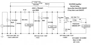
Here is a pentode-pentode amp with the Schade NFB, something I did in 2020. The DF looks OK. Pentodes without negative voltage FB have very poor DFs,My dim understanding of the best way to implement plate-grid feedback around an output stage is that you need the very high plate resistance and gain of a pentode for the driver tube and you want the higher gain of a pentode for the output stage. My understanding is that the idea is to get the output power of a pentode but without the phase shifts of the OPT inside the feedback loop.
What happens if you conduct the same experiment using something like a 6AC7 driving a 6L6, comparing 'Schade' NFB to global NFB?
I've not included the result of that here. Just look at the data sheet for the 6V6 & others, DF without NFB is ~Rl / rp.
Attachments
Norman Crowhurst makes that comment in one of his articles covering his Twin Coupled Amp.Feedback from the OPT primary also reduces distortion in the OPT, and improves its bandwidth. That part is great; it's the bit about loading the driver valve that isn't so great. One option is to bring the feedback a little further back to the cathode of the driver valve. DC is involved, so that cathode resistor needs adjusting, so an iterative approach works. Or could be calculated, but bulky.
All good fortune,
Chris
Think its in the first, I'll dig it out later. The proof must have been done sometime before that.
Distortion in the OT manifests as magnetizing current. (both the normal inductor current, saturation + Hysteresis current ) Which then makes for unwanted voltage drops across the output tube rp and the primary winding resistance. The local N Fdbk can fix the drop across the tube rp, but it doesn't see the winding resistance drop unless you have an auxiliary winding for the feedback source.
The winding resistance drop can be fixed by a positive current referenced Fdbk from a current sampling resistor below the output tube cathode(s). A high value (adjustable initially) Rfdbk resistor from that output cathode back to the associated driver cathode (above a low value R in the driver cathode) provides extra drive to the driver tube to compensate for the loss of voltage across the winding resistance for the current seen. Effectively nulling out the resistive V drop from magnetizing current and signal current as well ( Rfdbk adjusted to do so ), so that the V drop does not get passed on to the secondary. (loss + compensation boost = 0 ) Negative resistance essentially. It will also significantly improve the damping factor by removing the primary winding resistance. Audio Precision patent # US4614914 1986 by Bruce Hofer, as pointed out by Merlin a couple of years ago. Also, RDH4 page 354 and references (pg 402, Rodham, 1950 and pg 1478 Anspacher 1950 )
You do need to make sure the input signal will stay within the range the output tube(s) can handle, particularly the LF saturating region. The positive Fdbk will slam the tube drive if the output current goes into magnetic saturation or a shorted load. Some kind of Zener or stacked Schottky diodes limit on the pos. Fdbk perhaps.
Last edited:
Transformers need to be driven from a voltage source. The lower the source impedance the better is the ability
to handle the magnetizing current. A triode looks like a voltage source of sorts, far better than a pentode.
So NFB from the plate of a pentode does improve that.
Variable +ve FB from the OPT secondary lead to the speaker was used in many Electrovoice Amps
along with the normal -ve FB. So with pot(s) a wide range of DF is possible.
I did one of those internal +ve FB things, split load phase inverter K lead back to stage One K in a PP amp to get more gain.
With the extra gain more full loop FB was possible, better DF resulted.
And tried the +ve FB from current to the speaker with -FB as well. Current was sampled in a length of resistance wire.
An interesting experiment, watching the speaker resonant peak decrease as PFB was increase & actually inverting.
The internal impedance of the amp has become negative, (Cancel the Speaker VC R). Then to far, lots of oscillation.
There are some articles on that kind of thing in magazines from the toob era.
Tried those pre 1960 while working in the research lab. 🙂
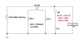
Here is the schematic simplified into plain English. The addition of these parts & a PS simply biases the tubes to their operating range.
The other method I used bypasses all that so that a designer can put together the bare bones to decide if the design should be pursued.
There are no pentode images in EWB, these are formed using MS Paint.
The other method I used bypasses all that so that a designer can put together the bare bones to decide if the design should be pursued.
There are no pentode images in EWB, these are formed using MS Paint.
Attachments
Hey Zin, at this age I'm too old to find my way thru Tubelab, altho it looks like a good way to go.@jhstewart9
may I ask you to implement the UNSET method by Tubelab as well?
Perhaps next time I go around tho! 😉
Here is Crowhurst's take on NFB from the OPT primary.Feedback from the OPT primary also reduces distortion in the OPT, and improves its bandwidth. That part is great; it's the bit about loading the driver valve that isn't so great. One option is to bring the feedback a little further back to the cathode of the driver valve. DC is involved, so that cathode resistor needs adjusting, so an iterative approach works. Or could be calculated, but bulky.
All good fortune,
Chris
Copied from Radio Electronics, November 1957, p42.
About 20 yrs ago I built two versions of Crowhurst's Twin-Cooupled Amplifier, the subject of that article.
In one a pair of 6LU8s in PP delivered 35 Watts at Clipping. On the plates +400V, the screens +300V.
D% & IMD results are very good. Like my other stuff it sits here on the shelf.
Attachments
- Home
- Amplifiers
- Tubes / Valves
- What Schade Feedback Leaves Behind