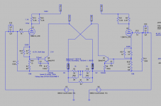
John Broskie posted, many years ago, a hybrid circlotron topology on tubecad. The interesting points about this design is it's a DC coupled tube-mosfet with dual feedback loops - one for the signal and a DC only loop.
Recently with an almost dead SS amp I was thinking if the fets were dead that a small hybrid would also fit quite nicely into the same chassis. Unfortunately all the fets survived and the amp is being recapped and tuned up. However the concept of using ECX10N20 which would have replaced the BUZ900P/905Ps with heavy biasing to operate in class AB got me thinking of updating the Cest Complique amp I have shelved whilst the world decided what it's going todo next. The beauty is that this is almost a roadkill style of build for me - salvaging or temporarily using components I have from various projects. Using smaller mains transformers is cheaper than a custom build HV transformer for a large number of tubes with complex heater-cathode requirements. So this is in modelling/design atm.
So my target is a class A hybrid circlotron able to support 8-55 ohm loads.

This is the power section, the 12BH7As provide a driver for the ECX10N20 that provides the grunt and finally the ECX10P20 provides DC offset control. The bias of the 12BH7A is about 9mA and the bias of ECX10N20 is a hefty 554mA currently. The idea was that the 12BH7A can take a 5Vpp input signal, although currently the system is running about -7Vg operating point at the 9mA.
I could spout THD/noise from LTSpice but the reality is I'll wait to see what the real components show. LTSpice shows 0.07% THD as it stands but there's still lots of design work and a front end required to add some character. The output, as you'd expect with a circlotron, is 3rd dominant but that's quite low.
With a 2Vpp input it's putting out 240mApp. So that's more than enough to destroy headphones.

I put the current into the FFT as I can't work out how to get LTSpice todo FFT if a maths expression, not sure if that's correct but it seems about right. Either way with a tube frontend that's likely to be completely irrelevant 😀
I've tried to compensate for the phase shifts by testing using a VO in one feedback loop rather than putting a second VO in the opposite side. Essentially I've split the bridging and tested/tuned one half and then replicating the changes to the other side. The DC low pass for the DC P-channel is tuned to 1.4Hz. I figured most headphones at that point would be heating too much so that's as accurate as it needs to be.
With 2Vpp input the response phase looks like this for either side:

I hope I have this right in using V(outB)-V(outA) but the resulting nyquist looks stable.
PS. Ignore the unity gain in the filename..
Recently with an almost dead SS amp I was thinking if the fets were dead that a small hybrid would also fit quite nicely into the same chassis. Unfortunately all the fets survived and the amp is being recapped and tuned up. However the concept of using ECX10N20 which would have replaced the BUZ900P/905Ps with heavy biasing to operate in class AB got me thinking of updating the Cest Complique amp I have shelved whilst the world decided what it's going todo next. The beauty is that this is almost a roadkill style of build for me - salvaging or temporarily using components I have from various projects. Using smaller mains transformers is cheaper than a custom build HV transformer for a large number of tubes with complex heater-cathode requirements. So this is in modelling/design atm.
So my target is a class A hybrid circlotron able to support 8-55 ohm loads.
This is the power section, the 12BH7As provide a driver for the ECX10N20 that provides the grunt and finally the ECX10P20 provides DC offset control. The bias of the 12BH7A is about 9mA and the bias of ECX10N20 is a hefty 554mA currently. The idea was that the 12BH7A can take a 5Vpp input signal, although currently the system is running about -7Vg operating point at the 9mA.
I could spout THD/noise from LTSpice but the reality is I'll wait to see what the real components show. LTSpice shows 0.07% THD as it stands but there's still lots of design work and a front end required to add some character. The output, as you'd expect with a circlotron, is 3rd dominant but that's quite low.
With a 2Vpp input it's putting out 240mApp. So that's more than enough to destroy headphones.
I put the current into the FFT as I can't work out how to get LTSpice todo FFT if a maths expression, not sure if that's correct but it seems about right. Either way with a tube frontend that's likely to be completely irrelevant 😀
I've tried to compensate for the phase shifts by testing using a VO in one feedback loop rather than putting a second VO in the opposite side. Essentially I've split the bridging and tested/tuned one half and then replicating the changes to the other side. The DC low pass for the DC P-channel is tuned to 1.4Hz. I figured most headphones at that point would be heating too much so that's as accurate as it needs to be.
With 2Vpp input the response phase looks like this for either side:
I hope I have this right in using V(outB)-V(outA) but the resulting nyquist looks stable.
PS. Ignore the unity gain in the filename..
Last edited:

I've been reading up on stability: http://www.iceamplifiers.co.uk/articles/stability/stability.pdf

I've treated one side of the load and grounded it with an AC source.

This seems stable as the nyquist diagram shows all the poles are on the left (stable) of the zero real line and not to the right (unstable).
I've treated one side of the load and grounded it with an AC source.
This seems stable as the nyquist diagram shows all the poles are on the left (stable) of the zero real line and not to the right (unstable).
Also figured out how todo maths with FFT in ltspice. Select the nets you want then do the FFT, once the FFT shows change the FFT to the maths you want with the nets, that way you can subtract FFTs etc:

Ok, I've been experimenting and have moved on from the original design into something more considered.

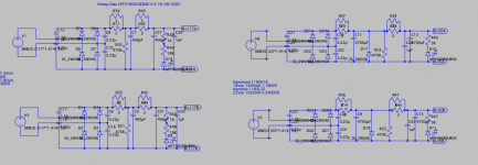
A Tube with a cathode following BJT. I've tried a lateral mosfet with a current mirror from the anode using a BJT and BJT-current mirror, I've tired BC335-40s in parallel and with a darlington driver but the package thermal limited the output to about 10-20mA.
The 12BH7A-STR is running at 9mA bias with about 155V across it, and the cathode bias is about +5V.
So I moved to a MJE243 to simply provide current drive. With a single device this seems to suit the requirements better. However I don't know the noise of the real devices just yet. A single device has more than enough current capability within it's thermal limits.
The configuration above is getting about 180mApp (~2.5Vpk) at 3.16Vpk input which is more than enough. It can go higher and be dropped down too without causing too much issue.
I was thinking of using a small p-channel mosfet as a DC servo from the other side of the load, replacing part or all of the 500R cathode resistor.
Simulated frequency response and noise seem good starting point. This is with 3.16Vpk input.

Lots of high level noise though but I suspect that's not really the main issue with a tube 🙂 I will simulate what happens with a tube short given it's a BJT.
EDIT: I forgot to say about the mosfet, that the issue is that it needs voltage swing (the profusion lateral mosfets have too low a cut off and transconductance to drive this low a signal without alot of current bias) - or at least I've not found the balance yet..
A Tube with a cathode following BJT. I've tried a lateral mosfet with a current mirror from the anode using a BJT and BJT-current mirror, I've tired BC335-40s in parallel and with a darlington driver but the package thermal limited the output to about 10-20mA.
The 12BH7A-STR is running at 9mA bias with about 155V across it, and the cathode bias is about +5V.
So I moved to a MJE243 to simply provide current drive. With a single device this seems to suit the requirements better. However I don't know the noise of the real devices just yet. A single device has more than enough current capability within it's thermal limits.
The configuration above is getting about 180mApp (~2.5Vpk) at 3.16Vpk input which is more than enough. It can go higher and be dropped down too without causing too much issue.
I was thinking of using a small p-channel mosfet as a DC servo from the other side of the load, replacing part or all of the 500R cathode resistor.
Simulated frequency response and noise seem good starting point. This is with 3.16Vpk input.
Lots of high level noise though but I suspect that's not really the main issue with a tube 🙂 I will simulate what happens with a tube short given it's a BJT.
EDIT: I forgot to say about the mosfet, that the issue is that it needs voltage swing (the profusion lateral mosfets have too low a cut off and transconductance to drive this low a signal without alot of current bias) - or at least I've not found the balance yet..
Last edited:
I'll remodel with the following transformers in mind:
Main power - each channel has a separate pair of toroids using separate secondaries with a simple RC low pass filter on them:
2x Hammond 1182E117 - 30VA 2x 256mA 117Vac secondaries, 12% reg and 53 DCR
2x Hammond 1182H18 - 30VA 2x 1600mA 18Vac secondaries, 11.7% reg and 1.18 DCR
Heaters, I have a 12.6V EI core that I may use for now but this caught my eye.
1xHammond 1182K12- 30VA 2x 2500mA 12Vac secondaries, 12% reg and 41.56 DCR
All the toroids are 3" round and 1.4" high making them nice and small for mounting. I may talk to Tiger Torroids here in the UK to see if they can combine the same specifications into a two single torroids - one for each channel. It's likely that the shipping will be cheaper rather than being dispatched from the US to the UK.
I may look at playing with other designs so having these will allow me to experiment.
The joys of tubes and circlotrons - cost. Well, when you focus on low noise resistors etc.
£320 including VAT @20%. That's including a large heatsink (12"/2.34" 1-2K/W), and a few extras that can be shared with a second channel. £100 of that is power toroids. The remaining parts of the power supplies are £30 each and channel (bar tube stuff I have) is £35. The MJEs shove out 15W each, so but I may tone that down later so all channels can share the heat sink. I've also added a diode for each PS to show when there's still voltage across the caps.
The weird doubling up for the caps is because 2uF gives a good frequency response but it appears getting 2uF is a PITA so two 1uF will do.
The doubling of resistors is to reduce noise but I may simply go single resistor to reduce costs for now. I may also remove the 1uF caps in the power supply for cost. The tube power supply will simply be 12.6Vac centre tapped non-toroid I have then use the circlotron to reduce any mains hum.
Combined with my EXC10Ns there's enough to make a nice little 10-25W class A hybrid valve amp too with a larger power supply. Also the toroids have enough current for voltage doubling too so I can play with the cascode already built for the case.
Attachments
Last edited:
I've been looking at single ended input performance and DC offset.
As you'd expect the performance halves as you don't have opposing side of the wave form. However you still have the opposing power supply noise (assuming you have near identical PS and transformer secondaries). This helps reduce hum and noise.
On the DC offset, I'm looking at few options:
a) use a low voltage P channel mosfet such as the VP2106 in the tube cathode supply with a ~1Hz low pass filter (1.6M+0.22uF) from the opposing side of the load. This just about works as the tubes are running at 5.5V and the threshold of the VP2106 is 5V. As long as the DC is within 0.5V then you're ok, the result is about 1-2mA deviation of the signal and if you believe a flattop FFT under 2Hz it's around 50uA:

After a second of running (6 secs of sim time) this reduces to 18uA:

That's with the amp running a 1V input 1KHz signal.
b) add a second tube to each side in a differential amp, then use the offset from the low pass filter. I quite like this idea..
c) opamp as a DC servo.
And two FFTs from the current schema when running single ended input:
Just on the signal side of the load:

With both the signal and the other side subtracted:

As you'd expect the performance halves as you don't have opposing side of the wave form. However you still have the opposing power supply noise (assuming you have near identical PS and transformer secondaries). This helps reduce hum and noise.
On the DC offset, I'm looking at few options:
a) use a low voltage P channel mosfet such as the VP2106 in the tube cathode supply with a ~1Hz low pass filter (1.6M+0.22uF) from the opposing side of the load. This just about works as the tubes are running at 5.5V and the threshold of the VP2106 is 5V. As long as the DC is within 0.5V then you're ok, the result is about 1-2mA deviation of the signal and if you believe a flattop FFT under 2Hz it's around 50uA:
After a second of running (6 secs of sim time) this reduces to 18uA:
That's with the amp running a 1V input 1KHz signal.
b) add a second tube to each side in a differential amp, then use the offset from the low pass filter. I quite like this idea..
c) opamp as a DC servo.
And two FFTs from the current schema when running single ended input:
Just on the signal side of the load:
With both the signal and the other side subtracted:
Last edited:
Parts ordered 🙂 in then end i had to ordet a new heater transformer due to the original EI transformer being used as a bucking transformer the 1950s receiver.
Looking forward to building it 🙂 I’m considering mounting it on ply first, then migrate to the chassis. Simply because it will be easier testing. The chassis is large enough to take all the transformers under the hood but that makes it harder to get probes in. Will have a think when the bits are here.
Looking forward to building it 🙂 I’m considering mounting it on ply first, then migrate to the chassis. Simply because it will be easier testing. The chassis is large enough to take all the transformers under the hood but that makes it harder to get probes in. Will have a think when the bits are here.
Last edited:
Tired after assisting for a 2 hour fight to catch a thresher shark (~4m long) on a two man 17ft boat (~5 meters long) on Saturday but I forgot to say the plan of action is simple - I've ordered enough parts for one mono channel. If that turns out good I will build the second channel. If the amp isn't great then there are enough parts to build a standard stereo amp and the parts I can use for testing new ideas (hence thinking about a flat ply test board initially with a top to protect components and ease of repositioning).
One of the transformers has a 10 day delay but that allows me to crack on with the receiver, then three of the power supplies (two HV and heater) and the tube section of the amp before the LV transformer arrives for the two remaining power supplies.
I've reduced the cost by £30 by switching some of the caps and the resistors, mainly by switching from the high hour rated to 3000-5000 hour in the power supplies and reducing the cost of the resistors by switching to single high wattage wire wound rather than paralleled 3W metal resistors etc. I managed to keep the bridge rectifier X caps, the parallel high quality low noise resistors in the signal path, the known brand caps etc. I even managed to increase the capacitance for the LV power supplies.
I updated the spice sim with the parameters from the order parts (capacitor 100Hz ESR, slight differences in uF etc etc):

Not too shabby. A DC offset of 1.5mV is acceptable given the I(Rload) shows a slightly better DC component:5.89667e-05.
.noise shows this (not sure how good this is as the resistors will be different):

DC component:-0.00147689
Total Harmonic Distortion: 0.004617%(0.004595%)
Not too shabby. A DC offset of 1.5mV is acceptable given the I(Rload) shows a slightly better DC component:5.89667e-05.
.noise shows this (not sure how good this is as the resistors will be different):
Now to play the game of will it fit.

There's one toroid on back order, end of the month but the two here are the HV and heater transformers.
There's one toroid on back order, end of the month but the two here are the HV and heater transformers.
This is my current thinking.

Transformers on top, IEC filter, caps and rectifiers underside. The 120VA transformers are over powered but they're for testing out new ideas. The amp itself could probably get away with less, making the transformers smaller or combined.
If it looks like a mini M60, you're right - the chassis was intended for a ec99 + 12BH7A implementation. It could be still but for now the same chassis fits the hybrid circlotron nicely.
Doh - it has occurred to me, if the DC + voltage swing of the B+ on both sides of the circlotron (and heater-cathode) then you could use one tube's pair of triodes per circlotron. Probably not suitable for higher voltage swings for speakers but for low impedance headphones that would be a power saving.
Looking at the chassis configuration for the m60 it did get me thinking about a cascaded circlotron for larger voltage swing to power ECX10N20 mosfets for speakers. I can try that configuration on the other side of the chassis at a later date.
Just thinking of the layout a little more:

With the transformers bolted through onto the top (at least for now), the area under them should be kept free of sharp screw heads etc to prevent any change of damaging the insulation.
Power comes in through the switched 2xfuse AC IEC line filter for all power supplies. The path of each power depends on the type:
Heaters: IEC -> transformer -> fuse -> Bridge rectifier -> resistor -> caps -> heater lines. This means the main IEC powers up the heaters immediately. The IEC switch then controls the amp totally and starts the pre-heat. There is a LED on the caps to show the heater line is currently has power due to cap charge. There's a bleed resistors here but the heaters will bleed the supply at 1-1.5mA.
HV: IEC -> illuminated power switch -> transformer -> 2x [ fuse -> bridge rectifier -> resistor -> cap -> resistor -> cap -> HV line ] this means that you can delay the B+ HV line power up (which should be quick) plus limit inrush. An LED on the caps shows power. Bleed resistor should bleed (1-1.5mA) off the power from the caps but will check to make it inline with the heaters bleed.
LV: IEC -> illuminated power switch -> transformer -> 2x [ fuse -> bridge rectifier -> resistor -> cap -> resistor -> cap -> LV line ] this means you have the option to delay the LV power. I may be tempted to simply combined the HV&LV power switches and also add a second fuse before the HV/LV line. An LED on the caps shows power. Again a bleed resistor should bleed ~1-1.5mA.
The location of the heater and LV PS will be against the side wall along with the LV+heater rails.
As this is experimental and early designs - In terms of safety should:
a) the headphone short - this does not result In a massive change to the amp although it will continue to provide current, it's not massive, it will drive the BJTs close to their maximum wattage. A possible option here is to monitor the BJT current delivery using an opamp over current lockout mute using a relay to protect them.
b) a tube short - this will result in about 390mA through the headphones currently, the current delivery doesn't cause a problem to the power supplies, mosfet or the BJT. The headphones would be toasted. So I need to look at options for this, however currently that's without a relay for the output. I will add a relay for power up muting so this could be tied in. A 5V voltage clamp (TVS or zener pair) across the headphone socket would be a good idea.
c) a tube open - this has exactly the same behaviour as a tube short.
This is why I have a 50 ohm load and a 50 ohm 2W test speaker and it's not going to be near my head for a while..
Looking at the chassis configuration for the m60 it did get me thinking about a cascaded circlotron for larger voltage swing to power ECX10N20 mosfets for speakers. I can try that configuration on the other side of the chassis at a later date.
Just thinking of the layout a little more:
With the transformers bolted through onto the top (at least for now), the area under them should be kept free of sharp screw heads etc to prevent any change of damaging the insulation.
Power comes in through the switched 2xfuse AC IEC line filter for all power supplies. The path of each power depends on the type:
Heaters: IEC -> transformer -> fuse -> Bridge rectifier -> resistor -> caps -> heater lines. This means the main IEC powers up the heaters immediately. The IEC switch then controls the amp totally and starts the pre-heat. There is a LED on the caps to show the heater line is currently has power due to cap charge. There's a bleed resistors here but the heaters will bleed the supply at 1-1.5mA.
HV: IEC -> illuminated power switch -> transformer -> 2x [ fuse -> bridge rectifier -> resistor -> cap -> resistor -> cap -> HV line ] this means that you can delay the B+ HV line power up (which should be quick) plus limit inrush. An LED on the caps shows power. Bleed resistor should bleed (1-1.5mA) off the power from the caps but will check to make it inline with the heaters bleed.
LV: IEC -> illuminated power switch -> transformer -> 2x [ fuse -> bridge rectifier -> resistor -> cap -> resistor -> cap -> LV line ] this means you have the option to delay the LV power. I may be tempted to simply combined the HV&LV power switches and also add a second fuse before the HV/LV line. An LED on the caps shows power. Again a bleed resistor should bleed ~1-1.5mA.
The location of the heater and LV PS will be against the side wall along with the LV+heater rails.
As this is experimental and early designs - In terms of safety should:
a) the headphone short - this does not result In a massive change to the amp although it will continue to provide current, it's not massive, it will drive the BJTs close to their maximum wattage. A possible option here is to monitor the BJT current delivery using an opamp over current lockout mute using a relay to protect them.
b) a tube short - this will result in about 390mA through the headphones currently, the current delivery doesn't cause a problem to the power supplies, mosfet or the BJT. The headphones would be toasted. So I need to look at options for this, however currently that's without a relay for the output. I will add a relay for power up muting so this could be tied in. A 5V voltage clamp (TVS or zener pair) across the headphone socket would be a good idea.
c) a tube open - this has exactly the same behaviour as a tube short.
This is why I have a 50 ohm load and a 50 ohm 2W test speaker and it's not going to be near my head for a while..
Looking forward to your build and comparison of reality with SPICE dreams ;-)
If it hits the side of the barn on the first attempt I'll be happy!
Heater power supply assembled, tested and works. This takes a while to discharge.
First HV power supply assembled, tested and works. No load this is showing 170Vdc, in the final position it will sit elevated on the LV power supply.
The LED safely light and bleed resistors work perfectly. Everything remains cool.
One point the amp will need a relay to disconnect on AC power failure - this is because the PS can discharge at different rates leading to imbalance. The same with turning the amp back on, as the PS may be in different levels of charge. So a timed relay start would be good.
Second HV power supply assembled, tested and working. I like the LEDs they're providing a good indication - the HV one is still dimly lit at 2.3Vdc.
Made a boo-boo in that I ordered a 5W 55K ohm instead of a 55 ohm load resistor.
Next job is to assemble the LV supplies. I can do this and test with a 13Vdc power supply I have but the LV transformer is backordered until later this month.
Made a boo-boo in that I ordered a 5W 55K ohm instead of a 55 ohm load resistor.
Next job is to assemble the LV supplies. I can do this and test with a 13Vdc power supply I have but the LV transformer is backordered until later this month.
Completed assembling the two LV power supplies.
Next up is finishing the mods to the case. It's occurred to be that my switches are single pole and not double pole (originally I was looking double pole for that reason but then forgot) and can't be used as each PS needs to be independent. I'm considering putting a small hole through the case to mount the NPNs directly to the heat sink and then rivet the HS to the side of the case.
I've been trying to plan the positioning of the components for the channel build - that is more complex given the distances.
So I've been compromising with the existing set of tube socket locations etc. I've decided to go with a single tube.

Now I may, for the first test simply use the socket to the left front. In reality it may have been easier to use a heatsink on the front (as originally envisaged for the M60 amp, the output signal would exit the four ecc99 tubes straight forward). I have a piece of HS that I could use for the mosfets if required with a simple screw+alu strip to hold against the HS. I'm trying to give myself some room initially for experimentation.
The idea is that the heater power (high current) is fed closest to the metal case. The LV higher current sits along the side. And the HV is fed over the top and down into the tube. That leaves the path from the tube to the BJT almost clear of power and quieter for the signal. In the end a better design would be to not be compromised by the existing positions.. but hey, you learn.
I also modelled the evil ecc99 and it works but, and here the but, the tube will result in a 16W BJT output rather than 11W for the BH7A which is over the 15W max. No benefit appears (which I'd expected), so back to the BH7A.
- Home
- Amplifiers
- Headphone Systems
- C'est Compliqué - Broskie Hybrid Tube Circlotron