i think its just the phot, when you look at the amp in the daylight it doesnt look like that.ok, good luck!
i see lots of charring in front of the heatsink
Well that should keep you busy 🙂 That burnt rectifier looks like it might supply just the lower voltage stuff. Strange sort of failure really but it could mean the power amp side of things is OK.
As always... use a bulb.
As always... use a bulb.
i did and its VERY bright 😱Well that should keep you busy 🙂 That burnt rectifier looks like it might supply just the lower voltage stuff. Strange sort of failure really but it could mean the power amp side of things is OK.
As always... use a bulb.
im realy looking forward to hearing this amp
Hopefully it is bright because of the failed rectifier and probable zapped cap. It is possible the voltage regulators (the one on which ever rail has failed) might possibly have suffered. It should be an easy repair (ha) but be prepared for collateral damage. Hopefully just the bridge and cap though.
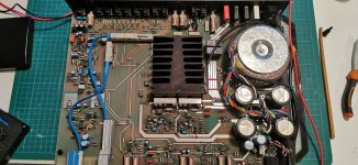
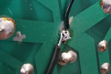
so first assesment then.There has been some real heat build up here to take off the top layer of the board exposing the fibreglass matting.
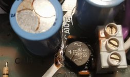
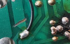
none of the solder joints were loose from what i can see, and the cap didnt actualy look that bad when i took it out, and still reads around the correct value at about 2180uf.I shall replace these.Not sure what make creek used, but these are all rubicon throughout
if you look carefully the print has lifted and my first thought is someone possibly put pressure on it pushing it away from the board,this would have shorted it out, if not immediatly, but over time moving and eventualy doing so maybe
i wont realy tell untill i have repaired it, which is going to be a challenge getting the track back, if its ok, or if not making something up, then fitting new parts, inc the the 2 filters and 4 ceramic caps that came out blackened, proberbly from the heat.
The transformer feed terminal block was slightly black, but not damaged and all terminals were tight.
its also had some kind of mod done to the grounding, which could have been done later.
Im going to ask mike creek if this would have been the case or if it was at manufacture.
never realy seen anything like this before with the rectifier,maybe some of you out there have?👍
Attachments
The grounding mod is most likely factory done, that kind of thing is really really common in all kinds of equipment as problems come to light in use out in the field.
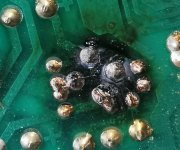
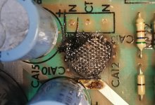
Any caps near the heat exposure area should be replaced. Its hard to say whether the failure of the rectifier caused the discolouration or whether the rectifier has been running hot all the time. Scorched and discoloured boards are not that uncommon in themselves. If it's r eally really bad and the board is 'carbonised' (which means it has become conductive) then its OK to drill/cut the bad area out and hard wire the new part in. That's more a problem in high voltage circuitry where carbonisation can lead to tracking and arcing along the board. The Creek is all low voltage in the scheme of things.
Any caps near the heat exposure area should be replaced. Its hard to say whether the failure of the rectifier caused the discolouration or whether the rectifier has been running hot all the time. Scorched and discoloured boards are not that uncommon in themselves. If it's r eally really bad and the board is 'carbonised' (which means it has become conductive) then its OK to drill/cut the bad area out and hard wire the new part in. That's more a problem in high voltage circuitry where carbonisation can lead to tracking and arcing along the board. The Creek is all low voltage in the scheme of things.
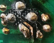
I can't make the numbers out tbh but if there are four of them and they connect across each arm of the bridge then they are most likely 0.1uF or 0.01uF and used to suppress 'commutation noise' as the diodes come out of conduction.
When the diode drops out of conduction the transformer winding can 'ring' and cause interference. The caps stop that and they are not critical at all in value but they must be able to withstand the required voltage. If the DC rail is for example -/+ 30 volts DC then the cap needs to at least 60 volts DC plus a good safety margin. So typically 160 volt or 250 volt working.
Do a web search and an image search for 'bridge rectifier snubber' 😉
Even a single cap across the secondary can be as effective and sometimes that might have a series low value resistor like a 2.2 ohm 0.5 watt carbon or metal film.
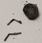
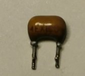
the markings are
4 EX IC
bit thanks ill have a look around
not going to be too easy this one, the drawings are not the same as what i have and it is all creek had, and they all look like drafts to me and not finalised as installed, most of the resistor references have ? against them, the capacitor references are 'c' NOT ca' and the rectifiers are different to what is installed.
i might uprate the current W005 to a W01 just in case it was under rated in the first place, im also going to uprate the filter caps from 25v to 35's or 50's depending on what will fit.
oh well all good fun, see how we get on 👍
Its certainly different to the NAD's you are used to. I dunno on the cap value tbh, those markings don't just register. Nothing on the other side of the cap?
A 0.1uF could be marked 104 which is 100,000pF and 0.01uF (103) is 10000pF.
A 0.1uF could be marked 104 which is 100,000pF and 0.01uF (103) is 10000pF.
They are probably all OK but if you are not happy then just replace them all. If we can't come up with a value then how about a something like 0.047uF which is a mid typical value.
Here's a trick 😉 if you can't see value then you can compare them using your scope and generator to known good values. Start with known good 0.1uF and set something up like this. The generator is to around 10kHz. Absolute values don't matter as you are comparing.
Here is what you would see with 0.1uF vs 0.01uF. The bigger the cap and the more it reduces the level.
I'll have a look I'm a bit wary at the moment with the generator since I blew that amp up with it
Hmmm... don't know how you managed that 😉 Such things are all part of the learning experience though and I've had lots of mishaps like that. As general rule amps don't like being tested at high frequency for long periods (at least at high outputs) and squarewave testing is hugely stressful for an amp at anthing more than a few volts output.
Testing the caps with the generator is 100% safe because no amp is involved. You just use the generator, the resistor and the cap under test.
Testing the caps with the generator is 100% safe because no amp is involved. You just use the generator, the resistor and the cap under test.
I think I had the amplitude up to high, it was about half way or about 5 to 6 volts peak to peak
There is a world of difference between an amp nominally rated at say 50 watts output and aimed purely at domestic use and one built to deliver that continuously under test bench conditions. Things get hot very very quickly under sine testing and even more so with square wave testing.
- Home
- Amplifiers
- Solid State
- Creek 5050