I built a VTA SP14 preamp which generates a 55dB 120 Hz hum a few inches from the woofers. That hum is audible at the listening position. This occurs when I use the SP14 with either a 200 or 400 watt solid state power amplifier driving 96 dB efficient speakers. If I use the SP14 with a First Watt M2x which is only 25 watts the hum is barely audible. I built the SP14 to use specifically with the Peachtree GaN 400 so the hum is a problem.
I have done everything I can with the SP14 to eliminate the hum which presumably is coming from some sort of ground loop or perhaps just a faulty design. The level of the hum is constant regardless of the volume control on the SP14 or the input from my DAC or anything else I change including wiring, transformers, or grounding so I have pretty much exhausted my options there and VTA doesn't have any suggestions.
It seems to me it should be possible to manage the hum by attenuating the output of the SP14 Preamp either before the GaN 400 amplifier or after the GaN 400 and before the speakers. But nobody seems to do this. In researching the problem it appears that the issues of attenuating after the preamp have to do with impedance, damping and distortion.
Does anybody have any suggestions about the best way to attenuate the output of the preamp to make the level of the hum inaudible without changing my power amplifier or speakers?
Thanks.
You certainly can do that, just keep the L-pad attenuator resistors near (or inside) the power amplifier.
Make the sum of the resistors equal to the smallest allowable load impedance on the preamp,
and make the attenuation somewhere from -6dB to -12dB. Include the loading effect
of the power amp on the attenuator, and use 1% metal film 1/4W resistors.
https://www.electronics-tutorials.ws/attenuators/l-pad-attenuator.html
For example, say the smallest load impedance allowed on the preamp is 40k, the power amp
input impedance is 20k, and you want -12dB attenuation. Then the shunt resistor could be 20k,
and the series resistor could be 30k.
Or you could use a regular volume control in a box, of the smallest value that the preamp works with.
Some older tube preamps did have two ganged volume controls per channel, one before the line amp,
and one after, to reduce the output noise.
You don't want an attenuator after the power amplifier (or to change the actual gain of the power amplifier).
That would cause all sorts of problems.
Last edited:
first guess is that the hum is a ground loop issue between the preamp and the power amp. If its worse with the larger amp, that's your clue.
Do you have access to a 'scope to look at and then for the source of the hum?
Do you have access to a 'scope to look at and then for the source of the hum?
Thanks Rayma.
So the input impedance of the GaN 400 is 100K ohms and there was no spec for minimum input impedance. I think the output impedance of the SP14 with 0.33 uF coupling caps is 600 ohms and that is meant to be usable with an amp with an input impedance of 50K ohms or greater. So if I am understanding your post correctly, for that combination of gear the sum of the series and shunt resistors has to be 50K ohms or greater? I looked at one L-Pad calculator and it came up with resistor values of 37.4K series and 16.8K shunt for 12dB attenuation. Do you think that would work without degrading the sound quality?
I didn't understand what you meant by using the smallest value of a pot that the preamp would work with. I am getting a 10K stepped attenuator this weekend but it sounds like that might be too low a value to work correctly?
Yes, that will give about -11dB attenuation, and should work well.
Those are close to, or equal to, standard 1% values.
If you try a volume control instead, it should be around 50k or 100k.
Again, all these should be located near or inside the power amplifier,
to avoid high frequency loss.
Does this noise happen from all line sources, or just from the turntable?
I believe the preamp lacks an internal RIAA stage.
Last edited:
I think it is a ground loop issue but I have put the power amp and preamp on the same circuit etc. etc. without any fix. And removing earth ground from the preamp had no effect. Moving transformers away from the PCB didn't help. All the wires are twisted. The ground on the inputs and outputs are tied together with a single wire which is only connected to the PCB at one point. Obviously the potentiometer is connected to PCB ground and then there is the earth ground connection so not much more to do there re a loop inside the preamp. Since I don't see any other fixes to attempt to alleviate the hum coming from the preamp that is why I am thinking attenuating the signal out of the amp would drive the noise floor below audible levels.first guess is that the hum is a ground loop issue between the preamp and the power amp. If its worse with the larger amp, that's your clue.
Do you have access to a 'scope to look at and then for the source of the hum?
Why not post some photos of the chassis? Is this a stock build as their manual advised,
or just made up from their pcbs?
or just made up from their pcbs?
Is this noise still present in the left speaker, if the right preamp cable is disconnected
(after turning the power off) from the power amp?
A shorting plug in the unused amp input is best for doing this test.
(after turning the power off) from the power amp?
A shorting plug in the unused amp input is best for doing this test.
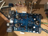
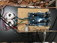
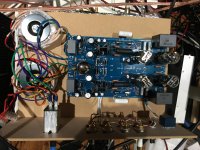
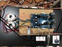
Here are some photos of the build. It was just made from their PCB but following their wiring diagram closely. Having the transformers close to or removed from the PCB made no difference. Disconnecting Earth Ground made no difference. Connections from the output capacitors to the RCA jacks is made with shielded cable. One cable is used for both right outputs and one cable is used for both left outputs. Shield is tied to the common ground on all the jacks for both cables but only one shield is also connected to the PCB ground per the instructions.
I disconnected the right output from the preamp and the noise was still present in the left speaker. No difference with or without shorting plug on the unused power amp input.
I disconnected the right output from the preamp and the noise was still present in the left speaker. No difference with or without shorting plug on the unused power amp input.
Attachments
Then there is not a noisy ground loop formed by connecting the preamp to the power amp.
However there could be an internal ground loop in the preamp itself, that increases the noise level.
Does the noise happen on all inputs, and in both channels?
Does it seem exactly identical in both channels, or somewhat different but about equal in volume?
However there could be an internal ground loop in the preamp itself, that increases the noise level.
Does the noise happen on all inputs, and in both channels?
Does it seem exactly identical in both channels, or somewhat different but about equal in volume?
The noise remains the same regardless of the input or output combination or whether I have grounding plugs on the unused jacks. The right channel is 2-3 dB quieter as measured 4" from the woofer. Moving wires around doesn't effect the noise. I haven't tried disconnecting the pot/inputs from the PCB. And all the grounds for the input and output jacks are tied together with a solid wire in a U shape that has one connection to the PCB via the shield of one of the speaker outputs. The original design called for a single straight wire but that wasn't possible with the Neutrik RCA jacks I used. I can't imagine why that would make a difference but ground loops are funny things.
What do you mean by:
a solid wire in a U shape that has one connection to the PCB via the shield of one of the speaker outputs.
Do you mean line output?
The noise is still there if no inputs are plugged in at all?
There are two separate stereo amps plugged into the preamp outputs all the time?
The noise is still present if only one of the amps is connected?
Last edited:
The noise is there even if there is nothing connected to either of the input jacks regardless of whether they have grounding plugs or not. So far I've only used it with one input but I have used it with one or two power amps without that having any impact.
Here is a picture of the jacks. There are two input jacks (closest to the pot) and two outputs. All of the ground terminals on the RCA jacks are connected by a single bare 18 awg wire that goes in a U because it isn't possible to do it in a straight line. The VTA chassis uses different RCA jacks where the grounding terminals can be lined up with a single straight bare wire but that design still calls for a common ground between the input and output jacks and just one connection to the PCB ground. The shield of the other cable is only connected to that common ground wire although I did try it with that shield connected to the PCB ground as well and it made no difference.
Here is a picture of the jacks. There are two input jacks (closest to the pot) and two outputs. All of the ground terminals on the RCA jacks are connected by a single bare 18 awg wire that goes in a U because it isn't possible to do it in a straight line. The VTA chassis uses different RCA jacks where the grounding terminals can be lined up with a single straight bare wire but that design still calls for a common ground between the input and output jacks and just one connection to the PCB ground. The shield of the other cable is only connected to that common ground wire although I did try it with that shield connected to the PCB ground as well and it made no difference.
Attachments

Possibly there is an inherent noise in the unit due to a common ground shared between channels.
Do you have a clear photo of the bottom of the assembled board? Also, what is the enclosure made of?
Do you have a clear photo of the bottom of the assembled board? Also, what is the enclosure made of?
Last edited:
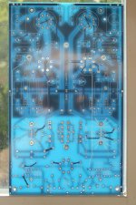
Here is the board, top and bottom views. The ground runs around the outside edge of the board but doesn't form a loop. The ground is common between both channels but I thought that was standard. If that is a problem it might be possible to cut the trace.
Attachments
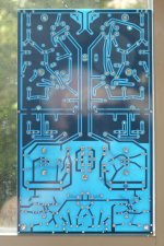
Can you describe the pcb mounts - is the metal on one side directly connected to the metal
on the other side, it all one piece? Is there an ohmic connection to the chassis from the top metal piece?
Can you post a part number, or a clear photo of the mount, it might be shorting something.
on the other side, it all one piece? Is there an ohmic connection to the chassis from the top metal piece?
Can you post a part number, or a clear photo of the mount, it might be shorting something.
Last edited:
I'm not sure I understand what you mean by the mounts but the PCB is held between two neoprene washers by a screw that goes into a brass standoff that is screwed into a piece of MDF. There is no metal chassis or anything that could be shorting anything out that I am aware of. And as far as I can tell all of the holes for the bolts are electrically isolated from the rest of the board.
I have changed all the tubes without any effect but is it possible that a capacitor, diode or voltage regulator could be introducing the noise into the circuit? I have no idea how I would even test for that.
I have changed all the tubes without any effect but is it possible that a capacitor, diode or voltage regulator could be introducing the noise into the circuit? I have no idea how I would even test for that.
Move both toroidals away from metal/steel at least 4 inches.
Need to ground the alps pot
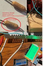
Check both resistors that connect from pin 3 and 6 to the ground
What voltage at pin 7 and 8 of all tubes?
What heater voltage? either 6.xx or 12.xx
Need to ground the alps pot
Check both resistors that connect from pin 3 and 6 to the ground
What voltage at pin 7 and 8 of all tubes?
What heater voltage? either 6.xx or 12.xx
Attachments
- Home
- Amplifiers
- Tubes / Valves
- Attenuation After Noisy Preamp?