Hi,
I'm very happy with my BH EL84, and today I tried to make my BH 6V6GT (working in AB2 at 340 V and 30 mA on a 8k Raa loadline) more similar to my sonic prefrences.
Actually the BH has three feedbacks:
- current cathode feedback on the phase splitter (a trimmer between the two cathodes and the ccs);
- 23% UL connections for output tubes' screens;
- 14% shade feedback on output tubes.
What I'd like to do is to add some nested feedback, so I went to search on the forum for... hey, there's no threads about it on the tube forum, let's open one!
I read Wavebourn that pushed alot on nested feedbacks, claiming better tha triode performance with negative feedback a-g1 on power tubes plus negative feedback from power tubes' a to drivers' cathodes plus variable positive current feedback from speaker's output to driver.
So I played a bit on LTspice and got interesting results (still to be applied in reality) with:
- current cathode feedback on the phase splitter (a trimmer between the two cathodes and the ccs);
- 23% UL connections for output tubes' screens;
- 30% shade feedback on output tubes;
- 820k from each output tube's anode to driver's cathode (phase splitter's ccs to be adjusted increasing its current accordingly);
- 220 mOhm on secondary winding, sending the signal to the opposite side of the phase splitter, with 470 Ohm to ground.
The interesting thing is that varying those values, harmonic "cascade" can be significantly changed.
Has anyone a recipe for different feedback ratios that gave him good results?
Thank you in advance
Roberto
If I could recommend something, it would be for you to insist that your thread be explicit that contributions be in terms of voltage or current derived / sensing and series or parallel injection. And that feedback levels be discussed in dB. Otherwise, it'll get annoying fast.
All good fortune,
Chris
All good fortune,
Chris
Thanks Chris, good point.
Only exception will be the UL, that will be espressed in % of voltage (more common than % of impedance).
Only exception will be the UL, that will be espressed in % of voltage (more common than % of impedance).
As possible examples of discussion there would be:
- Edward Cherry's nested feedback article;
- John Miller combining positive and negative feedback article;
- RCA 50W amp;
- Wolcott amps;
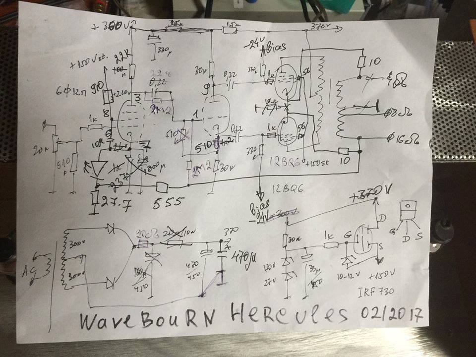
- Wavebourn amps;
- others...
Edward Cherry's nested feedback article can be found here: https://linearaudio.nl/sites/linearaudio.net/files/cherry ndfl.pdf
John Miller combined positive and negative feedback can be found here: https://linearaudio.nl/sites/linearaudio.net/files/miller combined fb electronics march 1950.pdf
The RCA 50 W amp is shown here:

Wolcott amps can be seen here: https://patentimages.storage.googleapis.com/2f/74/09/fc0dd530a5eff4/US3328711.pdf

One example of Wavebourn amps is shown here:
Making a living out of tubes? (A little off-topic)
- Edward Cherry's nested feedback article;
- John Miller combining positive and negative feedback article;
- RCA 50W amp;
- Wolcott amps;
- Wavebourn amps;
- others...
Edward Cherry's nested feedback article can be found here: https://linearaudio.nl/sites/linearaudio.net/files/cherry ndfl.pdf
John Miller combined positive and negative feedback can be found here: https://linearaudio.nl/sites/linearaudio.net/files/miller combined fb electronics march 1950.pdf
The RCA 50 W amp is shown here:
Wolcott amps can be seen here: https://patentimages.storage.googleapis.com/2f/74/09/fc0dd530a5eff4/US3328711.pdf
One example of Wavebourn amps is shown here:
Making a living out of tubes? (A little off-topic)
I attach here the results of the simulation and the LTSpice file to let other people play with it.

These the results at 23 Wrms
These the results at 23 Wrms
Code:
Harmonic	Frequency	 Fourier 	Normalized	 Phase  	Normalized
 Number 	  [Hz]   	Component	 Component	[degree]	Phase [deg]
    1   	1.000e+03	1.943e+01	1.000e+00	   -1.21°	    0.00°
    2   	2.000e+03	1.246e-02	6.410e-04	  -84.74°	  -83.53°
    3   	3.000e+03	1.206e+00	6.205e-02	   -1.42°	   -0.21°
    4   	4.000e+03	1.888e-02	9.714e-04	   83.36°	   84.57°
    5   	5.000e+03	2.817e-01	1.450e-02	  178.48°	  179.70°
    6   	6.000e+03	2.698e-03	1.388e-04	 -127.39°	 -126.18°
    7   	7.000e+03	2.654e-02	1.366e-03	 -129.43°	 -128.22°
    8   	8.000e+03	1.552e-03	7.989e-05	   54.75°	   55.97°
    9   	9.000e+03	3.357e-02	1.728e-03	   13.08°	   14.29°
Total Harmonic Distortion: 6.377368%(6.378897%)
Attachments
This is the THD at 1 Wrms (output impedance is 2.2 Ohm so DF is 3.6):
...and the THD at 16 Wrms:
of course it still needs to be optimized, I just want to share what made me open this thread about something that has been marginally talked about on this forum.
Code:
Harmonic	Frequency	 Fourier 	Normalized	 Phase  	Normalized
 Number 	  [Hz]   	Component	 Component	[degree]	Phase [deg]
    1   	1.000e+03	3.966e+00	1.000e+00	   -1.16°	    0.00°
    2   	2.000e+03	1.411e-03	3.557e-04	   86.25°	   87.41°
    3   	3.000e+03	1.357e-03	3.421e-04	  -12.12°	  -10.97°
    4   	4.000e+03	8.261e-06	2.083e-06	  127.40°	  128.56°
    5   	5.000e+03	1.697e-05	4.277e-06	  179.00°	  180.16°
    6   	6.000e+03	3.551e-06	8.952e-07	  177.04°	  178.20°
    7   	7.000e+03	2.968e-06	7.484e-07	  177.52°	  178.67°
    8   	8.000e+03	2.661e-06	6.710e-07	  177.49°	  178.65°
    9   	9.000e+03	2.362e-06	5.954e-07	  177.88°	  179.04°
Total Harmonic Distortion: 0.049350%(0.049343%)
...and the THD at 16 Wrms:
Code:
Harmonic	Frequency	 Fourier 	Normalized	 Phase  	Normalized
 Number 	  [Hz]   	Component	 Component	[degree]	Phase [deg]
    1   	1.000e+03	1.582e+01	1.000e+00	   -1.13°	    0.00°
    2   	2.000e+03	1.217e-02	7.695e-04	   82.54°	   83.67°
    3   	3.000e+03	2.288e-01	1.446e-02	   -4.38°	   -3.25°
    4   	4.000e+03	4.374e-03	2.765e-04	   91.74°	   92.87°
    5   	5.000e+03	4.885e-02	3.088e-03	 -175.55°	 -174.41°
    6   	6.000e+03	1.146e-03	7.245e-05	  -79.13°	  -77.99°
    7   	7.000e+03	1.583e-02	1.001e-03	   14.84°	   15.97°
    8   	8.000e+03	4.364e-04	2.758e-05	  105.60°	  106.73°
    9   	9.000e+03	8.021e-03	5.070e-04	 -159.20°	 -158.06°
Total Harmonic Distortion: 1.485515%(1.485833%)
of course it still needs to be optimized, I just want to share what made me open this thread about something that has been marginally talked about on this forum.
Please help me understand the term: "Nested Feedback"
I thought nested feedback usually meant that one (*) negative feedback was somewhere in the middle of the amplifier circuitry.
And then another negative feedback was in a loop that included circuits that were both before the (*) negative feedback, and after the (*) negative feedback.
In other words, the (*) feedback was "nested" somewhere in the middle of the outer feedback loop.
It only takes 2 negative feedback loops with one that is in the middle of the other feedback loop, to call it 'nested feedback'.
Right?
Last edited:
Zintolo,
You are very energetic!
I see a lot of complexity to your amplifier:
Feedback:
2 UL; 2 plate to cathode; 1 global; and 2 DC in the bias string.
That is 7 loops.
2 LEDs, 6 Bipolar NPNs, 2 N-Channel MOSFETs, and 2 Zeners . . .
. . . 12 solid state devices
And . . .
. . . 3 tubes
When is a tube amplifier almost not a tube amplifier?
Is there a Hybrid category anywhere?
Dear 6A3sUMMER,
Your assumption on mested feedback is right.
I’ve just added feedback resistors to a schematic developed by others on this forum before my arrival. It is the Baby Huey.
Your assumption on mested feedback is right.
I’ve just added feedback resistors to a schematic developed by others on this forum before my arrival. It is the Baby Huey.
About nested feedback, I suggest, for inner loop, insert a small cap in serial of the feedback resistor, so that it is only engaged at high frequency, and you get more feedback on global loop at audio frequency. It helps your THD, if you care.
It is not “the more feedback loops, the better” game. The goal is to have as much as feedback on the globe feedback. Thus, you can get most error corrected. Local feedbacks tend to reduce the open loop gain, and reduce the global feedback. It does not help THD figure.
Sometimes, the open loop gain is too much, which leads global loop unstable, the designer often uses local feedback to reduce the open loop gain, especially at high frequency.
Sometimes, the open loop gain is too much, which leads global loop unstable, the designer often uses local feedback to reduce the open loop gain, especially at high frequency.
About nested feedback, I suggest, for inner loop, insert a small cap in serial of the feedback resistor, so that it is only engaged at high frequency, and you get more feedback on global loop at audio frequency. It helps your THD, if you care.
Thank you very much jxdking, I will try it as well.
Thanks again, I would say "the more feedback loops, the more complicated it becomes to find the right balance between all of them".It is not “the more feedback loops, the better” game. [omissis] It does not help THD figure.
More than THD alone, I would like to see how this can shape the slope of the harmonics and make the distortion "more acceptable" to ears, even if not the lowest.
But this it's just me, and other people may be chasing other aspects, including lowest possible THD.
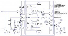
This is another interesting feedback typology (sorry it's in French, I will resume here for simplicity.
The ideator (as far as I know) is the user arnaud (aka iriaax):
Transfo de sortie Supersonic W8 en correction differentielle - 6bm8-lab.fr

The so called differential correction compares the scaled down signal at the output of the amp with the signal at its inlet, and feedbacks the difference between the two. So at low power (and so low distortion) the feedback is almost nothing, whilst at high power (and so high distortion) the gain is used to correct the distortion.

Filtering at both infeeds of the feedback are set to correct variation in phase of the signal.

So this is the full feedback schematic, reinjected at the other side of the PI.
Has anyone ever done something similar on his amps?
I've planned to try it, and all people seems positively impressed by it.
Thanks for your feedback.
The ideator (as far as I know) is the user arnaud (aka iriaax):
Transfo de sortie Supersonic W8 en correction differentielle - 6bm8-lab.fr
The so called differential correction compares the scaled down signal at the output of the amp with the signal at its inlet, and feedbacks the difference between the two. So at low power (and so low distortion) the feedback is almost nothing, whilst at high power (and so high distortion) the gain is used to correct the distortion.
Filtering at both infeeds of the feedback are set to correct variation in phase of the signal.
So this is the full feedback schematic, reinjected at the other side of the PI.
Has anyone ever done something similar on his amps?
I've planned to try it, and all people seems positively impressed by it.
Thanks for your feedback.
zintolo,
You said: "people seems positively impressed by it."
Did of those people post any test results of such an amplifier?
Or, are the people just impressed with the concept?
Seems awfully complex to me, and subject to the consequences of phase problems, especially when picking one output transformer, versus another output transformer.
Using the output tubes in Pentode mode, gives lots of power efficiency, and lots of gain; but also gives very high plate resistance, rp.
So, the frequency response and phase at both low frequencies, and at high frequencies is very dependent on the output transformer.
That complicates the stability when negative feedback is applied.
And different loudspeakers phase/impedance curves further complicates it.
The variable 22k feedback resistor to get the gains to match is a good idea, but it also changes the phase of the negative feedback because the 180pF is a fixed value.
I count 9 poles. That is including the matched poles of the RC couplings to the output tubes, and the almost matched poles at the input circuit (12k 40pF, 12k 40pF, not a perfect match, because one drives the other). That does not even include the 4 Triode's Miller Effect capacitances poles.
You also said:
"The so called differential correction compares the scaled down signal at the output of the amp with the signal at its inlet, and feedbacks the difference between the two. So at low power (and so low distortion) the feedback is almost nothing, whilst at high power (and so high distortion) the gain is used to correct the distortion."
Well, that is the same effect as a lot of other negative feedback systems.
Just my opinions.
Last edited:
zintolo,
Thanks!
But, I do not understand French.
1. I did look at the links you pointed to. There were some other variations of the special circuit that you posted; one had the same low pass filter from the input, and the negative feedback signal, but this time with only one triode to compare the difference, and to send the correction signal to the LTP grid.
I look at those circuits, and what I see is just another method to apply negative feedback.
I was not able to make any conclusions about power levels, 2nd and 3rd harmonic distortion, 2nd and 3rd intermodulation distortion, damping versus frequency, and stability.
2. Years ago, I presented a different amplifier circuit that I thought was unique.
But then I was told the French did the same as the circuit I thought was unique, but they did it years before I did.
3. I think the lesson to me is, basically there is nothing new under the sun; there are only new combinations of the old things.
Last edited:
Google permits you to translate full sites as well: Google Translate
What is different from standard feedback methods, is that it only starts to apply feedback when the amp start to distort. When the amp is clean, the amp has no feedback at all: there no signal on the other side of the PI.
And when there's feedback, it just applies the distortion as feedback and not the full distorted signal as feedback.
I've never seen something similar before, but maybe others did.
That's why I asked.
Presenting harmonic profiles is not very illuminating, especially for playing off one N Fdbk versus another.
I suggest graphing the amplifier gain versus input signal V level from -Vin to +Vin (across max limits). Use a horizontal line across the graph for nominal gain, and scale the vertical for something like +/-1% (or less) variation from nominal. Now you will see the effect of each adjustment on the gain curve shape, and can make judgments on playing one adjustment off against another for cancellation of gain deviation. (for equal V steps at the input, the relative gain is just the differential step heights at the output)
This same scheme can be easily applied for an actual amplifier too. Just feed a triangle waveform into the amplifier (has a constant differential), and differentiate the output of the amplifier (which would be a constant for constant gain). The triangle wave also gets sent to the O'scope horizontal, and the output differential gets sent to the O'scope vertical (AC coupled to eliminate the large nominal gain factor) with O'scope gain set to max.
Another classic amplifier with nested loops was the Citation II.
Last edited:
The differential N Feedback scheme is the same as "Error Correction". (originally developed for tubes by Llewellyn, 1941 US patent 2,245,598, but only became popular for SS when Malcolm Hawksford wrote articles on it)
It has been shown to be equivalent to conventional N Fdbk with very high loop gain from a positive Fdbk inner loop. If you look at the scheme carefully you will find there is a positive Fdbk path in it, that just makes the loop gain very high.
A major illusion is in forgetting that the differencing circuit has distortion too.
And practically, one has to adjust the gain difference attenuator to perfection, or it becomes an oscillator. The infinite loop gain occurs right at the oscillation point.
Last edited:
- Home
- Amplifiers
- Tubes / Valves
- Nested feedback: best practices (Baby Huey and beyond)