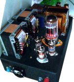
Now my kids have grown up a little, I am enjoying working through my accumulated stash of bits and pieces. I decided I had the parts to make a 6080 amp, something I always fancied, and being lazy in my old age and curious of the rare design, I decide to make an amp to the Hi Fi world 6080 circuit.

I was disappointed with the resulting amplifier. The two problems that troubled me were due to the ECC88 cascode. Its weedy 100k pull up gave bad slewing problems, and the unpredictable DC operating condition, brought to my attention by two randomly selected ECC88, resulted in one channel clipping high side, and the other clipping low. Not impressed.
Put the amp to one side as I pondered alternative destinies for the amplifier. Since that failure I started on some other ideas, gratuitously rats nested this time, including the SRPP circuit. Revisiting the dp circuit I realised I could change the the cascode to a SRPP. So I did, I had to pull the top valve up a bit to get symmetry, and not being familiar with the SRPP there could be a better way.
I have had various (recycled vintage) power transformer misadventures with this amp, but the first one gave me 5 watts at 5% distortion. It was getting a bit hot, so I have a lower voltage one and I now get 3.5 watts, but it works very nicely, and I would tentatively call it my current favorite amplifier. It is dynamic, it has good solid bass, and strangely to me, it gives me the best imaging from my speakers I have ever heard.
The feedback works to keep the HF up, although the amp still struggles with slewing, at least its symmetrical and can get to 20kHz sine wave. Square wave looks generally clean. I am using a multi tapped SE output transformer with the 8 ohm load on the 16 ohm tap, to give me a 1k1 primary impedance.
Attachments
hbc,
Looks great.
Congratulations on the superb imaging.
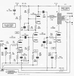
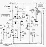
If you get a chance, please put up a schematic of the amplifier.
Thanks!
Looks great.
Congratulations on the superb imaging.
If you get a chance, please put up a schematic of the amplifier.
Thanks!
This will work, thanks !
In case you are not expecting any DC on the input of this amp you can remove C1 and connect VR1 directly to the switch.
In case you are not expecting any DC on the input of this amp you can remove C1 and connect VR1 directly to the switch.
Last edited:
hbc,
Thanks for the corrected schematic.
Please help me understand why the 47k negative feedback resistor from the 8 Ohm output tap drives 2 points in the amplifier:
The input tube cathode (makes sense).
. . . And the output tube grid (at high enough frequencies that the 5pf can overcome the SRPP tube's cathode impedance; but the series 47k feedback resistor can not overcome SRPP's cathode impedance.
Seems like the 680k and 5 pf need to be returned to ground, instead of to the 47k.
And that raises the question, does the SRPP cathode need to see a 5pF load?
Thanks!
Last edited:
Lampie519,
You are correct.
I overlooked the bootstrap effect.
The SRPP cathode out probably has an output impedance of around 100 or 200 Ohms.
That cathode drives a 0.1uF cap, which drives 680k in parallel with 5pF.
Without the bootstrap, the -3dB point of that network is 2.3Hz, or -1dB at 4.6Hz.
And, any 200 Ohm SRPP output impedance can drive 680K just fine.
Seems like the bootstrap does not have much effect, except for music that is lower than 5Hz (record warp signal of 3 Hz?, or 6Hz canon on the Telarc recording of the 1812 overture).
Last edited:
The bootstrap will increase the virtual input impedance of the power tube considerably (as the grid leak resistor is riding on it). Therefore the load for the driver will be less and thus less distortion.
Last edited:
Any SRPP driver that can not drive a grid leak resistor of 680k, without significant distortion probably should be re-designed.
But for those who worry about 680K Ohms over-loading an ECC88 cathode, they need to have their worries put to rest, so they can sleep at night.
But for those who worry about 680K Ohms over-loading an ECC88 cathode, they need to have their worries put to rest, so they can sleep at night.
Last edited:
True but now there is almost no load at all making the SRPP super linear...
I can sleep at night... Thanks for worrying,
I can sleep at night... Thanks for worrying,
At really low frequencies, the bootstrap feedback will have leading phase, and will be rolling off.
At really high frequencies, the bootstrap feedback will have lagging phase, and will be rolling off.
SRPP super linear at . . . mid frequencies.
Bootstrapping from the secondary of an output transformer . . .
Is not the same as a cathode follower that is bootstrapping its own grid leak resistor.
At really high frequencies, the bootstrap feedback will have lagging phase, and will be rolling off.
SRPP super linear at . . . mid frequencies.
Bootstrapping from the secondary of an output transformer . . .
Is not the same as a cathode follower that is bootstrapping its own grid leak resistor.
Last edited:
hbc,
Thanks for the corrected schematic.
Please help me understand why the 47k negative feedback resistor from the 8 Ohm output tap drives 2 points in the amplifier:
The input tube cathode (makes sense).
. . . And the output tube grid (at high enough frequencies that the 5pf can overcome the SRPP tube's cathode impedance; but the series 47k feedback resistor can not overcome SRPP's cathode impedance.
Seems like the 680k and 5 pf need to be returned to ground, instead of to the 47k.
And that raises the question, does the SRPP cathode need to see a 5pF load?
Thanks!
Please forgive me for my circuit editing omissions earlier. I thought it would be easier to mod the existing circuit. There is another, in my version I did not see a need for the 5pf. My impression of the 680k is that it provides some feedback from SRPP in my case, or what would have been the 100k resistor / top of the ECC88 cascode. It needs to swing about 150v pk-pk to get full output. It is quite possible that dp's output transformer was better than the one I am using, and the 5pf could be to tame the HF a little.
I had to pull up V3 to get enough voltage swing without it clipping. There may be a better way of doing it.
Last edited:
The boot strap helps but too small to be very effective. I used 1/2 the plate swing, this loos like 1/12th.
- Home
- Amplifiers
- Tubes / Valves
- Tim De Paravicini's HiFi World 6080 amp modded by me.