Ok how can I use 1400 uf 350 VDC computer grade electrolytic capacitor(s) in a tube amp power supply. The company my son works for installs server farms and they have a case of NOS never used 1400 uf 350 VDC computer power supply capacitors heading for the dumpster. I told him to grab it for me. I was thinking as part of a brute force power supply for a preamp or amp running on under 300 volts. They are Sprague capacitors so not Chinese crap.
Totally unsuitable for your application. The current draw to charge them is too great to be of any use.
That sort of capacitor is used in magnet charging coils for small electric motors or UPS systems.
That sort of capacitor is used in magnet charging coils for small electric motors or UPS systems.
Are those the blue ones with the screw terminals?
They are cool but like JonSnell Electronic already mentioned, the current draw to charge those behemoths is really high so you would probably need some kind of current limiting during startup to avoid burning up your transformer/pop fuses.
They are cool but like JonSnell Electronic already mentioned, the current draw to charge those behemoths is really high so you would probably need some kind of current limiting during startup to avoid burning up your transformer/pop fuses.
A choke input power supply wouldn’t have as bad a start up surge. Still much more capacitance than required for a preamp. Might be about right for two in series, for a big power amp running off 600V. With a soft-start circuit.
They are suitable with careful design and mechanical construction. Mind you they are extremely dangerous!
I use 2 x 8x photoflash capacitors in my preamplifier, 1000uF/450V each (8 in each channel). This is an overkill. They have been in service for than 25 years now. I limit the charging current by placing a big 1k resistor after the bridge rectifier. A bleeding resistor to GND is absolutely mandatory. Calculate the charge and discharge time. T=RxC, but this formula gives 63% discharging, 37% remains in after T!
In my tube monoblocks I use 8x 220uF/450V, more than enough.
Are those the blue ones with the screw terminals?
They are cool but like JonSnell Electronic already mentioned, the current draw to charge those behemoths is really high so you would probably need some kind of current limiting during startup to avoid burning up your transformer/pop fuses.
Yes blue Sprague's with screw terminals they are approx 7-8 inches long and 2 inches in diameter.
Totally unsuitable for your application. The current draw to charge them is too great to be of any use.
That sort of capacitor is used in magnet charging coils for small electric motors or UPS systems.
Yes he told me the technicians had these as spares for large (think closet-sized) UPS systems. I'll probably just tell my son to ebay them, he can use the cash. They sound way too wicked/dangerous for a hobbyist at my skill level.
thanks everybody
Going crazy with extreme over-capacitance for tube amplifiers is not beneficial.
Depending on the style of rectification (tube/SS) voltage sags and hum are no issue at all with only 50 to 100uF feeding the output transformer(s).
Every amp I've serviced comes out hum-free, with excellent performance.
This obsessive "capacitor craze" that I hear about being "more is better" has gotten rediculous.
These were all the rage in the late 90s, and as you can see so far in this thread, there are some good reasons that we don't use them anymore!
In series, where B+ is over 300vdc, they would be 700 uF. That is not so extreme as the second gap in a PSU? Or 470uF with 3 in series?
Having managed to get a jolt picking up an amplifier with no tubes and no baseplate, I would be petrified I’d have an accident with them. A dead amplifier seems so much more innocuous than one powered up.
Having managed to get a jolt picking up an amplifier with no tubes and no baseplate, I would be petrified I’d have an accident with them. A dead amplifier seems so much more innocuous than one powered up.
Windcrest77, how old are those?
If they're 20+ years old and have never been used, they most likely have been deteriorated beyond any reforming possibilities.
If they're 20+ years old and have never been used, they most likely have been deteriorated beyond any reforming possibilities.
700 uf is still pretty extreme, unless the tube amp you’re building is 200 watts per channel. Some of us might be inclined to do just that, but most are too chicken (or too cheap, or too smart, or some combination thereof).
700 uf is still pretty extreme, unless the tube amp you’re building is 200 watts per channel. Some of us might be inclined to do just that, but most are too chicken (or too cheap, or too smart, or some combination thereof).
So, to paraphrase another quote (motorcyclists, I think) ... there are old tube fans, and there are bold tube fans, but there are not old bold tube fans ;-)
Windcrest77, how old are those?
If they're 20+ years old and have never been used, they most likely have been deteriorated beyond any reforming possibilities.
Good point, I'll have to ask my son to ask one of the techs if they know. Or maybe they have date codes. I wouldn't want to go through the trouble of reforming them.
Many years ago I got a box full of similar caps, except that they were bigger and rated for 450 volts. They can be used in a tube amp, but have a lot of stored energy which can do bad things when something goes wrong.
I found that a reasonably sized electrolytic in parallel with a polypropylene motor run cap actually has a lower impedance over a wider frequency range. My big electrolytics found their way into a friends ham radio amp and I haven't looked back.
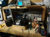
I know of at least one.......
Don't try this at home kids, there is 1500 volts in that yellow Radio Shack clip lead, and the power supply is rated for 1500 volts at half an amp. The big rectangular cap at the end of the lead was stolen from a cardiac defibrillator.
I found that a reasonably sized electrolytic in parallel with a polypropylene motor run cap actually has a lower impedance over a wider frequency range. My big electrolytics found their way into a friends ham radio amp and I haven't looked back.
there are old tube fans, and there are bold tube fans, but there are not old bold tube fans ;-
I know of at least one.......
Don't try this at home kids, there is 1500 volts in that yellow Radio Shack clip lead, and the power supply is rated for 1500 volts at half an amp. The big rectangular cap at the end of the lead was stolen from a cardiac defibrillator.
Attachments
I don't know goats… 1400 µF isn't really “too large” except from an “abuse of a simplistic rectifier tube(s)” perspective. Which is easily remedied to almost no down-stream effect by a series resistor between the rectifier(s) and the first bank of capacitors.
OR, since I'm a really big fan of CLCXC designs (L = inductor, X = regulator), I enthusiastically recommend the large values for the middle 'C'. The inductor completely protects the rectifier stack from overcurrent surges (provided that C1 is rationally smallish).
The 'X' both reduces any residual ripple to inaudible values, but also stabilizes the delivered B+ to a basalt-rock-solid constant value, independent of one's line voltage variations and other unpredictable indelicacies.
⋅-⋅-⋅ Just saying, ⋅-⋅-⋅
⋅-=≡ GoatGuy ✓ ≡=-⋅
I use a 1000 uF 650 Volt electrolytic capacitor as first capacitor after my bridge (and before a MOSFET gyrator, etc., etc.). I have an inrush current limiter in my mains wiring. This is used for a 600 VDC regulated @ 500 mA class A amplifier (still under construction). The power supply is stable and has been tested hundreds of times already.
Regards, Gerrit
Regards, Gerrit
For energy storage, it’s not really about ripple, it’s more related to impedance at 20 Hz. My latest big amp was 200 watts (monoblock) with two 1000 uf in series. OPT was 1.9k a-a, which is a 475 ohm load. It is effectively like using 30000 uf on 8 ohms which is only a bit on the high side, not severe overkill. 22000 uf is typical for a high-current solid state monoblock, and about right for a 2 channel Touring grade PA amp. Probably could get away with using 250uF, but I doubt I’d go with less. Want stereo? It would be about the right amount of C.
The 800 watt in early development? Ra-a is 1kohm. That will want 1000 uf, considering it is going to be driving subwoofers.
You don’t want anything like that discharging uncontrollably.
The 800 watt in early development? Ra-a is 1kohm. That will want 1000 uf, considering it is going to be driving subwoofers.
You don’t want anything like that discharging uncontrollably.
- Home
- Amplifiers
- Tubes / Valves
- 1400 uf 350 VDC computer grade electrolytic