Have a JL Audio e1800DM monoblock that has a protection/shut down issue. The amplifier was playing normally until a very heavy note was required, then the protection light would flash very briefly, the amp would power down and restart and the whole cycle would repeat as long as that level of output was required. If the volume was turned down just under that level, it would continue to play uninterrupted.
I tested it on the bench with a 2ohm dummy load and a 50hz test tone. Output was continuous and uninterrupted until the voltage at the + input block read under 9v due to my small power supply and mains current limiting bulbs, which were full brightness before the amp would restart. I checked/resoldered all the legs of the heatsink mounted components and solder joints but yielding no results.
I tested the amp in the vehicle afterwards and monitored the + input terminal voltage but the amp still shuts down on heavy bass notes even with + input voltage not dropping below 12v. The rail voltage was around +88v with 14.3v on the + input block. I have no idea what can be causing this.
A self inflicted wound occurred while trying to check the rail voltage during testing. The meter probe slipped in between the buss bars and contacted the board which blew up Q31. I can only read IRL___ and the rest is missing. It is likely a logic level FET.
What is Q31? I can only begin troubleshooting when this is replaced but possible causes of the initial issue would be welcome now.
As far as I know, the only logic level FET they use is the one for the low-voltage supply. They used the IRLZ34N as well as others.
The only logic level FETs I have are IRL540N and IRF3709Z. Any idea if one of these might work? Is there anything a bit more common/easy-to-find that can work in this position?
The 540 is the only one of those two that would work.
Mouser has 5000 of the right part in stock.
IRLZ34NPBF Infineon datasheet and CAD model download | Octopart
Mouser has 5000 of the right part in stock.
IRLZ34NPBF Infineon datasheet and CAD model download | Octopart
Replaced Q31 with IRL540N and repaired separated trace under the rail buss bars but amp not fully functional. The green led turns on when remote power is applied but there is no PS gate voltage and no rail voltage. Various voltages are posted below with remote on. LEDs D11 and D12 are not illuminated and are connected in series directly to the trace that was separated and repaired. That trace shows 2.17v when remote power is applied. I will continue researching other posts in the meanwhile...
UC3525ADW
1) 0
2) 5.0
3) 0.1
4) 0.3
5) 2.1
6) 3.8
7) 2.0
8) 0
9) 5.7
10) 0
11) 0
12) 0
13) 11.9
14) 0
15) 12.0
16) 5.0
LM319M closest to UC3525
1) 0
2) 0
3) 0
4) 2.3
5) 3.7
6) 0
7) 0
8) 0
9) 0
10) 0
11) 12.0
12) 0.2
13) 0
14) 0
IRL540N Q31
1) 1.2
2) 13.5
3) 0
UC3525ADW
1) 0
2) 5.0
3) 0.1
4) 0.3
5) 2.1
6) 3.8
7) 2.0
8) 0
9) 5.7
10) 0
11) 0
12) 0
13) 11.9
14) 0
15) 12.0
16) 5.0
LM319M closest to UC3525
1) 0
2) 0
3) 0
4) 2.3
5) 3.7
6) 0
7) 0
8) 0
9) 0
10) 0
11) 12.0
12) 0.2
13) 0
14) 0
IRL540N Q31
1) 1.2
2) 13.5
3) 0
So I got the power supply and rail voltage back by replacing the LM317T and both transistors at Q7 with 2SB1260. I now have gate drive at PS FETs and +80v of rail at the rectifiers.
However, I have no output. With the black meter lead on input GND, the red probe reads +11v at the output terminals. All four LEDs slide to the rectifiers are illuminated and the LED on the driver board is illuminated also.
However, I have no output. With the black meter lead on input GND, the red probe reads +11v at the output terminals. All four LEDs slide to the rectifiers are illuminated and the LED on the driver board is illuminated also.
Input ground? Do you mean the primary (B+) ground or the shield ground?
Do you have 80v at the output transistors? These amp have a habit of breaking the leads on the rectifiers.
Do you have 80v at the output transistors? These amp have a habit of breaking the leads on the rectifiers.
Rail voltage is at the outputs. But there seems to be no gate drive. With the black probe on the primary GND, the following voltages were taken from the output transistors.
Q104, Q107, Q108, Q111
1) 0.1
2) +82
3) 0.1
Q105, Q109, Q106, Q110
1) 4.3
2) 0.1
3) 0
Q104, Q107, Q108, Q111
1) 0.1
2) +82
3) 0.1
Q105, Q109, Q106, Q110
1) 4.3
2) 0.1
3) 0
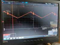
Yes, I have a triangle waveform on pin6 of the NE555.
Attachments
Last edited:
If you apply remote then remove it, do you have any drive pulses on the gates of the output FETs? You should have about 10-15 seconds to check after removing remote voltage.
The amp has an intermittent issue. It wasn't working properly at one point reading 7v, 11v, and 18v at the speaker + and - terminals with the black probe on Power GND terminal. I used the scope and got drive signals on the first gate of each output pair and a square wave on the gates of the second output of each pair. During this troubleshooting various different symptoms were displayed including a time when the protection light was just flickering on and off repeatedly.
The amp is currently working properly with 40v on both + and - speaker terminals, although the readings are different by just under 1v. Tested in the vehicle and it is able to play clean bass up until the same high demand where it cuts out like it did originally. The protection light flickering issue did occur once during this period but I am wondering if I am able to track down the shutting off issue, that solution might solve the protection light flickering issue as well.
I monitored various voltages in the amp while testing it in the vehicle. The + and - input voltage did not drop below 12v. The + and - speaker terminal voltage did not drop below 38v. The +-15v did not drop on op amps. PS FETs gate drive did not exceed 4.7v. I do not know what to check/monitor when the amp protects and resets itself. It is just unable to drive the subwoofer with any more force after a certain point.
Can some light be shed on the protection circuit for this amp? Thinking that maybe I could monitor the inputs and outputs of whatever IC is being used for protection purposes to try to figure out where/why this shutdown is occurring?
I don't see anything operationally wrong with the amp and I resoldered almost everything suspicious. The amp works perfectly up until very high current draw is required...
I don't see anything operationally wrong with the amp and I resoldered almost everything suspicious. The amp works perfectly up until very high current draw is required...
Are you sure that you have sufficient supply capacity?
These amps are VERY sensitive to voltage drop and a multimeter is very rarely fast enough to catch the dips in voltage that will cause them to shut down.
These amps are VERY sensitive to voltage drop and a multimeter is very rarely fast enough to catch the dips in voltage that will cause them to shut down.
There is definitely something wrong with this amplifier. The amplifier is unable to produce a hard bass note without the protection light flashing and the amp restarting. I just tested it in the vehicle and the voltmeter connected across the battery + and - inputs never dropped below 14.05 and the amp was cutting off. No other amplifier has a problem with these same wires, including my daily driver JL 1000/1 which should be just as sensitive. This is the original problem that it was brought to me because of.
There has to be something triggering this shutdown but I just don't know what to look at or monitor. It acts as if there is a loosely soldered power input connector that is unable to supply the current demand of the amplifier. But I checked and resoldered everything that I could see on this board..
There has to be something triggering this shutdown but I just don't know what to look at or monitor. It acts as if there is a loosely soldered power input connector that is unable to supply the current demand of the amplifier. But I checked and resoldered everything that I could see on this board..
Last edited:
I never had this problem with one of these and they're different than the slash and other amps of the era. I'd look for a comparator (or op-amp) with a reference voltage on one input and a voltage that varied with the 12v supply voltage on the other input. The only comparator I see in the power supply area is the LM319.
- Home
- General Interest
- Car Audio
- JL Audio E1800DM