Ok so story on this one was blown power and audio section.
Right now the rectifiers are pulled and a 2 ohm resistor in series with 12v power. No current draw.
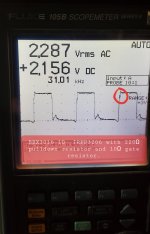
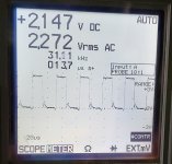
I am trying to understand what the attached waveforms are telling me, if they are ok and how to clean them up if they're not.
Replaced R106 and R107 on the Pwm card.
I didnt have any irf064ns but i did have a ton of IRFP3206's on hand.
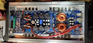
8 Mosfets in power section changed to Irfp3206.
Gate resistors changed to 10Ω down from 22Ω.
8 drivers replaced with bd139 and bd140. Originally were the C3228 and complimentary pnp.
8 power supply Fets replaced from IRFP064N'S to IRFP3206.
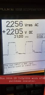
4 pulldown resistors reduced from 470Ω to 220Ω which helped pul back down to ground.
Right now the rectifiers are pulled and a 2 ohm resistor in series with 12v power. No current draw.
I am trying to understand what the attached waveforms are telling me, if they are ok and how to clean them up if they're not.
Replaced R106 and R107 on the Pwm card.
I didnt have any irf064ns but i did have a ton of IRFP3206's on hand.
8 Mosfets in power section changed to Irfp3206.
Gate resistors changed to 10Ω down from 22Ω.
8 drivers replaced with bd139 and bd140. Originally were the C3228 and complimentary pnp.
8 power supply Fets replaced from IRFP064N'S to IRFP3206.
4 pulldown resistors reduced from 470Ω to 220Ω which helped pul back down to ground.
Attachments

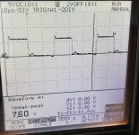
Were those waveforms with the scope probe ground on the source leg and the probe on the gate leg. If not, repost with that configuration.
I am gone from the shop for the day but i believe the source of the 3206 is connected directly to ground and the ground lead wad clipped to the ground rail. I am not positive ill have to check tomorrow and clip it to the source leg.
Last edited:

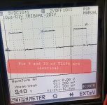
I removed the 2ohm current limiter.
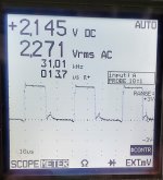
Here is the correct waveform with B+ voltage at 12.05V.
See Attached.
Here is the correct waveform with B+ voltage at 12.05V.
See Attached.
Attachments
Last edited:
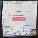
The amplitude is still low. What is the DC voltage on the collector of the NPN driver transistors?
I did re-insert 2 ohm current limiter so i did not slip the probe and blow components.See attached.
Attachments
Last edited:
That's a LOT of drop. What's the resistance between the base of the drivers and pins 9 and 10 of the 494?
Are you saying that there is a difference in the resistance between the output terminals of the 494 to their respective driver bases?
Yes. I am assuming you mean pin 10 is driving this pair of NPNs i am referencing at 262Ω.
If i measure pin 9 of TL494 to the base of the other set of NPNs i am getting 263.8Ω.
I have been taking measurements from the drivers group driving the bank of irf3206 i referenced with low amplitude. I cant see the designations on the board because of the limited space.
If i measure pin 9 of TL494 to the base of the other set of NPNs i am getting 263.8Ω.
I have been taking measurements from the drivers group driving the bank of irf3206 i referenced with low amplitude. I cant see the designations on the board because of the limited space.
Attachments
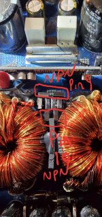
This amp is driving 2 NPN/PNP pairs per 9/10 pin. I have an NPN/PNP combo driving 2 IRF3206's. I have a total of 8 mosfets with 2 drivers per 2 mosfets. Its more similar to the AQ20 schematic.
Attachments
Last edited:
- Home
- General Interest
- Car Audio
- Hifonics BRX 3016.1D waveforms