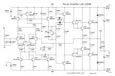
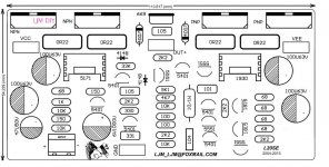
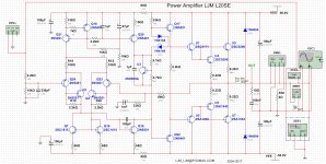
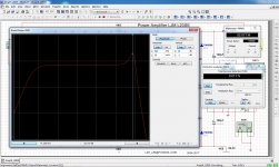
Electronic Schema Power Amplifier LJM L20SE
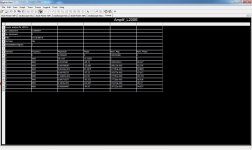
Electronic schema and analysis
Schema: Amplif_L20SE.pdf - Google Drive
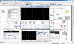
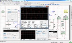
Project: Amplif_L20SE.ms14 - Google Drive
I am not marketing this product and I am not the author of the project. I did the schematic circuit for analyzing and sharing information.
Electronic schema and analysis
Schema: Amplif_L20SE.pdf - Google Drive
Project: Amplif_L20SE.ms14 - Google Drive
I am not marketing this product and I am not the author of the project. I did the schematic circuit for analyzing and sharing information.
Last edited:

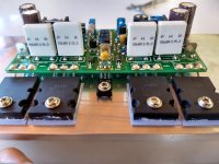
I bought one on aliexpress and also tried to solve the puzzle. What I found is identical except for one detail: I can't find the 33k resistor between VEE and the base of the 2N5401pre-driver: your schematic counts 29 resistors, the actual board only 28. (at least, the version I received).

I think its a perfect amplifier ,can outperform commercial ones of many 1000 .Of course needs coupling input capacitor ,adjustable bias current at 25ma per transistor and nothing else.At 35-0-35 AC don't need to change the value of 150 Ω resistor ,maybe at higher power supply.
I had a quick look at the circuit.
* What is the phase and gain margin?
* Where is the short circuit protection?
* HDS662 has to temperature compensate 6 VBE's
* current source with 270 Ohm resistor and 2N5401 will not be stable with severe ambient temperature changes!
* where is the offset-null trimming?
* where is the quiescent current trimming?
* 1n4004 are not very fast diodes for freewheeling transients!
* 1mF capacitor in the feedback path ?
Location of the original L20SE thread
The original L20SE thread, started by LJM (the board designer), may be found at:
http://www.diyaudio.com/forums/solid-state/199093-l20-amp-use-only-two-njw0302g-5.html#post3601502
The original L20SE thread, started by LJM (the board designer), may be found at:
http://www.diyaudio.com/forums/solid-state/199093-l20-amp-use-only-two-njw0302g-5.html#post3601502
I'm sorry
🙁 You are correct, this resistor does not exist, there are only 28 resistors.I bought one on aliexpress and also tried to solve the puzzle. What I found is identical except for one detail: I can't find the 33k resistor between VEE and the base of the 2N5401pre-driver: your schematic counts 29 resistors, the actual board only 28. (at least, the version I received).
Electronic Scheme Power Amplifier LJM L20SE
Electronic schema for analysis
Attachments
Image
Images
Images
Attachments
-
 IMG_20180408_125409741_HDR.jpg627 KB · Views: 1,202
 -
 IMG_20180408_125318453_HDR.jpg697.5 KB · Views: 1,361
 -
 IMG_20180408_125445511.jpg593.2 KB · Views: 1,110
 -
 IMG_20180408_125504180_HDR.jpg746.8 KB · Views: 1,071
 -
 IMG_20180506_160902796_HDR.jpg691.4 KB · Views: 1,061
 -
 IMG_20180506_161003796.jpg676.7 KB · Views: 878
Hi Eliseu
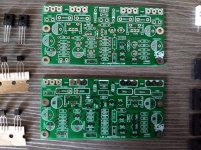
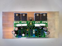
greetings very nice build is it possible to post correct schematic
warm regards
Andrew
greetings very nice build is it possible to post correct schematic
warm regards
Andrew
Eliseu,
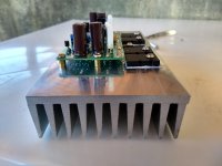
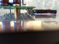
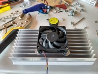
Thermal grease is not used with rubber washers. Just bare washer between transistor and heatsink.
Thermal grease is not used with rubber washers. Just bare washer between transistor and heatsink.
Eliseu,
Thermal grease is not used with rubber washers. Just bare washer between transistor and heatsink.
Good observation! In the last modification in the project I took out the folder. Soon I'll be posted. Thank you!
Hi Eliseu
greetings very nice build is it possible to post correct schematic
warm regards
Andrew
Yes. The original has been corrected and the project has been added. It's at the beginning. Page 1.
- Home
- Amplifiers
- Solid State
- Power Amplifier LJM L20SE