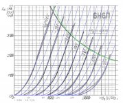
Here is some sheets about 6N6P russian double triode noval base tube.
I was working on spice model for my bunch of tube models, have spoted
some notes about the tube that could be of interest for the future experiments with 6N6P tube.
Txt file contains datas fro manode chrs. graph. (GraphClick.app used for extracting values from the graph)
I was working on spice model for my bunch of tube models, have spoted
some notes about the tube that could be of interest for the future experiments with 6N6P tube.
Txt file contains datas fro manode chrs. graph. (GraphClick.app used for extracting values from the graph)
Attachments

there is global PSpice model for all region showed in the datas. I compare two sources of datas and they are pretty same with minor differences.
.m file is Matlab file for module with Tuparam. m file from Norman Koren site.
You can download the file from his site and find additional useful informations
about modeling in spice for tubes. GraphClick file for 6N6P tube graph is a bigger file and I can send via mail, just ask (mac osx app.)
.m file is Matlab file for module with Tuparam. m file from Norman Koren site.
You can download the file from his site and find additional useful informations
about modeling in spice for tubes. GraphClick file for 6N6P tube graph is a bigger file and I can send via mail, just ask (mac osx app.)
Attachments
Last edited:
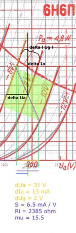
The suggestion for the setting the working point for smaler signals input
like for instance line preamplifier stage or 1st stage in power amplifier...

I found some interesting region at the chrs graph. In that region tube is
particularly linear. Also 6N6P can accept the signal of about 4Vp-p at the input.
With aminimum distortion.
What is from the character and bit of unusual,
is that the load line can be set with a value equal of Ri (internal resistance of the tube in working point)
or even a little bit less from Ri value.
And with the same portions of current amplifying values as well as voltage values.
And the load line angle is 45deg from 90deg line to the Anode Ia/Ua -8V Ug line.
Which is could not be accomplished with every point in the region
.
like for instance line preamplifier stage or 1st stage in power amplifier...
I found some interesting region at the chrs graph. In that region tube is
particularly linear. Also 6N6P can accept the signal of about 4Vp-p at the input.
With aminimum distortion.
What is from the character and bit of unusual,
is that the load line can be set with a value equal of Ri (internal resistance of the tube in working point)
or even a little bit less from Ri value.
And with the same portions of current amplifying values as well as voltage values.
And the load line angle is 45deg from 90deg line to the Anode Ia/Ua -8V Ug line.
Which is could not be accomplished with every point in the region
.
Attachments
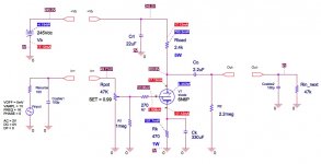
You can find from the picture static point datas and tube chrs in point of use
with load lines. Ri is about 2.4K and load could be even 2.2K less than Ri.
With Ri of 2.4K the load line is with 45deg against the Ia curve.
Cdynamic is the value calculated with gain in point, and about 0.7pF added for the socket
...
with load lines. Ri is about 2.4K and load could be even 2.2K less than Ri.
With Ri of 2.4K the load line is with 45deg against the Ia curve.
Cdynamic is the value calculated with gain in point, and about 0.7pF added for the socket
...
Last edited:
What do you think about the 6S7B triode ...Here is some sheets about 6N6P russian double triode noval base tube.
I was working on spice model for my bunch of tube models, have spoted
some notes about the tube that could be of interest for the future experiments with 6N6P tube.
Txt file contains datas fro manode chrs. graph. (GraphClick.app used for extracting values from the graph)
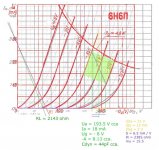
This is a strange "subminiature tube" but I believe it is a fantastic one and it cost about nothing on eBay ...
The curves are very linear all over a 350V peak to peak output swing with just - 3,25V bias at 300V 3ma (0,9W) operating point (the maximum Ua) ... So the gain is very high ! It have a 1,45W maximum dissipation and 7ma current. I evaluate the dynamic plate resistance to about 25K at this point, like a 12AY7.
I think I will buy some this winter for tests, they cost about 40$ for a lot of 10 and less than 15$ for two ... It is easy to hookup them on a small "terminal strip" inside the amplifier frame.
Alain. 😀
Last edited:
Alain
I did not have any experiance with this type, but over the very quick look at the pdf,
it seems that is more than OK?
Yes it is linear, but not over the wider region, just about the 1Vp-p input voltage
and it will be in the higher Va pole of about 250V from max. 300V Va.
and the Ia of about 4.5mA (strange thing, factory recommended values are not always friendly with "audio best" values for the same type...)
.
the tube showing a not so small tollerances of mu and other units, so You can expect
some drift from original datas. Probably it is the best way to measure curves for real specimen?
.
And tube is very tolerant to shock and vibrations, extremly, which could lead to the notion that the internal construction and materials are very good. but like other miniature tubes has les value of working hours 1500 from the pdf...
cheers
Last edited:
there are some graphs of
Bandwith
output resistance
Voltage FFT
And Current FFT
.
Tube showing very low level of THD even with full pot
and lower output resistance (1160 ohms) for small tube stage
cheers
Bandwith
output resistance
Voltage FFT
And Current FFT
.
Tube showing very low level of THD even with full pot
and lower output resistance (1160 ohms) for small tube stage
cheers
Attachments
I will put the same circuit with Inductive load
for transformer or choke load operation
and post results...
for transformer or choke load operation
and post results...
This is the circuit datas for Reactive load, like transformer with load of 2.4K.
For the solid range of bandwidth minimum inductance is about30 [Hy].
against maximum capacitance transferred at anode side of about 680 [pF],
which is not an unbearable question, but it is not so easy to achieve.
.
Cheers
For the solid range of bandwidth minimum inductance is about30 [Hy].
against maximum capacitance transferred at anode side of about 680 [pF],
which is not an unbearable question, but it is not so easy to achieve.
.
Cheers
PDFs from Transformer Loaded 6N6P in line preamplifier circuit mode...
The datas showing even less distortion compare to low distortion with classic R load...😀
But the results are obtained with simple equivalent circuit, without core issues
or transfer ratio. Just total approximated values.
The datas showing even less distortion compare to low distortion with classic R load...😀
But the results are obtained with simple equivalent circuit, without core issues
or transfer ratio. Just total approximated values.
Attachments
I can check some results from the same operating point, with choke load,
and maybe with constant current source.
cheers
and maybe with constant current source.
cheers
From the previous datas I found another tube which could be loaded with the same
value like internal resistance. 6N30P russian tube
value like internal resistance. 6N30P russian tube
I used the 6N6P Spice model you presented.
It gives mu=16.5 only. According the Soviet data sheet mu shoud be around 22.
My test circuit was CCS loaded common cathode amp.
It gives mu=16.5 only. According the Soviet data sheet mu shoud be around 22.
My test circuit was CCS loaded common cathode amp.
I checked the mu again from two different specifications and looked it from the anode curves. Those show some 17...18.5 indeed.
Artosalo, mu is amplification factor of the tube
and it is the figure that it is not constant over the whole region.
mu is changing value with respect to point of operation.
And in the datashets mu is given like sort of average value.
.
Another thing is that mu, like amplification factor, and -A, stage gain is not the same thing at all.
amplification of the stage or stage gain or whatever You can call it
is the figure that is always smaller than the mu of the tube.
Mu of the tube is from static datas on paper.
Against the stage gain that represents tube in real dynamic environment,
in real circuit.
So mu and -A (negative mark before A is from phase reversal...)
are not the same figures, and should not be the same, -A is always lower than mu
in CSS mode and Choke loaded tube, -A is little bit closer to mu then in other load fashions.
And You can find Yourself mu with the tubes datas of anode chrs.
from the graph. That method is the same for every classic style triode.
I post it at the first side.
.
mu is dUa/dUg in choosen point of operation.
from the graph. That method is the same for every classic style triode.
I post it at the first side.
.
mu is dUa/dUg in choosen point of operation.
Artosalo, mu is amplification factor of the tube
and it is the figure that it is not constant over the whole region.
mu is changing value with respect to point of operation.
And in the datashets mu is given like sort of average value.
Thanks for free lesson 😀.
My point however was that is the mu of actual 6N6P tube that low. I had an image that 6N6P and ECC99 (JJ) would be similar (mu = some 22), but after checking some of my old measuring results too ( with CCS as anode load) it seems that mu is well below 20.
-A is always lower than mu
in CSS mode and Choke loaded tube, -A is little bit closer to mu then in other load fashions.
Would you please clarify what you mean.
- Home
- Amplifiers
- Tubes / Valves
- 6N6P tube - focus on