

So I had everything working and connected to the ACA, sounded open and beautiful, but after a couple minutes I started to see smoke. So I realized I made a mistake by not taking the last thermistor mentioned to the same grounding point as the grounding points. So I fixed that and now when I used my multimeter everything still looks right. But now when I plug it in I get the ACA, I have the LEDs light up, but no sound. The ACA still works with the original power supply. I’ve got around 33 volts inside the Linear PSU at the connectors. I had to use an adapter on the cable because I got the size wrong on the barrel out of my PSU. So my best guess is that something is up with my connectors? Is there any good way to test the voltage at the connector? It seems dangerous to do that.Is the power supply working properly now, with no sparks?
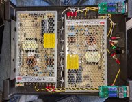
I see that you connected the ground lift thermistor to the negative of the bridge rectifier. That is not the proper location for the thermistor. It should be connected to the output ground of the power supply, at the last capacitor, and then to the chassis ground.
What gauge are your wires? They look quite small diameter in your pictures.
I see that you twisted the transformer wires together. That is a good thing. However the other wires are not twisted together, which is not a good thing. The AC wires, live and neutral, from the IEC connector should be twisted together. The DC wires from the bridge rectifier to the power supply filter capacitors should be twisted together. The DC wires from the power supply output to the connector on the back of the chassis should be twisted together. This to minimize noise.
Pictures please, and a sketch of your power supply showing components and wiring. I see you have a bridge rectifier for each transformer secondary winding but it is difficult to see how they are wired so a sketch would be helpful.
Power transformer secondary winding specified voltage?
Power transformer secondary winding specified voltage?
I hope it’s ok that I used the First Watt wiring diagram to start from as it was my go by when putting this together. I couldn’t verify the Voltage rating of the bridge rectifier which is why there are question marks next to it. I verified everything with a check mark next to it.
It turns out it was the adapter. I bought another one and everything is working now. Sounds wonderful. Thanks for all the help.
The bridge rectifier rating is most likely more than adequate based on its size.
The 33V measured at the power supply output is in the ballpark for the 25VAC transformer.
Where was the smokecoming from when you were listening to the amplifier with the linear supply attached?
I see multiple capacitors at the IEC connector. What are these capacitors connected to? I cannot see how they are connected. Are they Class X? Your schematic shows only one capacitor.
Edit: I see you have it working now. I am still wondering about the capacitors at the IEC connector.
It’s tough to read in the installed position but what I think it says is
SA101K
X1 300W
Y2 300W
18 M15
Sorry about missing that on the schematic. The capacitors connect the on side to the off side of the switch for both + and -.
I didn’t see where the smoke was coming from. The chassis was closed up when it happened.
SA101K
X1 300W
Y2 300W
18 M15
Sorry about missing that on the schematic. The capacitors connect the on side to the off side of the switch for both + and -.
I didn’t see where the smoke was coming from. The chassis was closed up when it happened.
Your capacitors have the correct rating, so that is good.
I am not sure how you have connected the capacitors from your desciption.
You only need one capacitor and it should be connected with one lead to AC live and the other lead to AC neutral.
I am not sure how you have connected the capacitors from your desciption.
You only need one capacitor and it should be connected with one lead to AC live and the other lead to AC neutral.
@Ben Mah: I may be wrong, but it seems that ahaiden is using capacitors across each side of the DPST power switch contacts, to quench arcs at switching on and off.
The capacitor that you are referring to, shown on the schematic as C9 (for line noise suppression and switch on/off thump reduction): if it also has a blue body, then appears to be half hidden by some leads from the power entry module (PEM).
Personally, as I really dislike cramped areas where it is difficult to troubleshoot and correct mistakes/blown components, I would not have located the thermistor block so close to the PEM.

Thanks, yes those capacitors are not the C9 capacitor, I believe they are for arc suppression. I started this project over a year ago and had to shelve it till now, so I didn’t totally remember what they were for when I first started again. I installed them because of another guide I had found elsewhere which mentioned doing it. But if did things again, I would not install them like that, nor let things get so cramped in ther, and I would get a chassis with more room, because I still plan to add capacitors to this one to power a second ACA for monoblocks, which is why it is a bit cramped. Thanks so much for your help, I really appreciate the insights that everyone shares here.
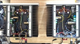
Hi Chris..took your lead and built my dual Meanwell PS with the Brijac version of the MJ's AmyAlice filter. All in an old Dynaco ST-120 amp chassis. . This drives a pair of parallel ACA monoblocks built using the mods by TA. The beefier Meanwell units don't make the strange little noises the "LRS-150" units make when first powering up the ACAs.hi TA
Can you give me a hint please where the pcb from Rudi can be found. you refered in post 1385?
is here a PCB -gerber available about ACA with TA mods?
sound after amyalice -SMPS filter:
i want to share my experience with this SMPS filter:
my setup is still small. i use a meanwell LRS 24V/150W SMPS brick in a seperate housing. I filtered every channel with this filter. the rail on the amp pcb is 24V and the DC point is 12,5V. i use the zerozone pcb with TA mods in a small chineses housing with 1,5A bias . MOSFETS are IRF044N and i am happy with the darkness of the tuning.
you should try this !!
SMPS Filter - AmyAlice
chris
Maybe dual LPSs in the future just because...
Cheers
Attachments
Just an update...I built two units with the TA mods incorporating the additions mentioned in my post above. Running them in parallel mode. I need to upgrade the resistors at R9 to 1.2K since I used IXTQ75N10P at Q1 and may want to go higher than 24V in the future, especially with a LPS. My big alteration to the ACAs, after a bit of listening, was subbing Nichicon UES 10uF non-polars at C3. I though the Silmics muffled the higher end a bit (I have a bias against them in the signal path..just my thing) while UESs seemed to brighten things up a bit.Folks, just want your opinions on my potential build for my ACA.
The typical TungstenAudio mods and :
R3&4 - 0.56R
Q1 - IXTQ75N10P
Q2 - IRFP140
C3 - Silmic II 10uF 50V (had them in my stash)
24VDC via a Meanwell PS for now but will eventually assemble a linear power supply (regulated or straight?)
12-12.5V bias ok?
R5&6 will stay at 100R
R9 - will stay at 1K unless go higher than 24V in
C1 - Nichicon KG 4700uF 35V (LKG1V472MESZBK)
Q4 - 2SK170 from the diyaudio store
R16 - 200R (unless I want to use higher voltage in)
Will incorporate an ACA Supply Filter by rhthatcher but will also build the MJ AmyAlice DC filter board to try
I think I got all of the particulars right
Many thanks, Pete
These monoblocks, with the TA mods and set up in parallel mode, really do sound exceptional. My first experience with a Class A amp. The pair also warm a small room nicely...;>). Thanks to everyone in this sub-forum who contributed with comments and/or pics. A fun little, easy-to-build project.
Cheers, Pete
Attachments
This is because they're a fundamentally different SMPS topology. The 200 watt units aren't flybacks.The beefier Meanwell units don't make the strange little noises the "LRS-150" units make when first powering up the ACAs.
Is that to my advantage with the ACAs or it's just a circuitry design difference?This is because they're a fundamentally different SMPS topology. The 200 watt units aren't flybacks.
- Home
- Amplifiers
- Pass Labs
- ACA amp with premium parts