Thank you TungstenAudio! It certainly was interesting/exhausting reading through the forum posts and deciding which path to head down which makes it fun/nerve wracking. So R9 would jump to ~1.2K and R16 would go to 400-600R if I use the 300VA+24V secondaries? How about adjusting DC balance (which I incorrectly termed "bias")? How high can I go with these chips & heatsinks? Many thanks again..
I wouldn’t change R9. R16 can be increased to the range you mentioned. The voltage on the Drain of Q1 would be increased along with a higher supply voltage.
My CRCRC values were 24mF/0.1R, 15mF/0.1R, 15mF.
My CRCRC values were 24mF/0.1R, 15mF/0.1R, 15mF.

Hello all, after having to take a two year hiatus, I’m back to working on this. I came back to my linear psu crcrc configuration and had some questions. When looking at the Aleph J PSU which I’m using as a guide (excepting that I’ll end up with two sets of +25V supplies), I’m confused by the wiring of the toroid . The two wires that are tied together with a thermistor, are those black of one to black of the other, or red to one to black of the other?
Also, I have a small capacitor that ties from the plug prongs to the other set of prongs that then go to the toroid. I remember doing a lot of reading not only on this forum but elsewhere to be sure I knew what was going on first, and I know I wouldn’t have added that just out of my own head. But I was hoping someone could help me figure out why I did this.
As I’m looking at my point to point connectors, it looks and feels rather cheap to me and I don’t particularly trust it. I was wondering if anyone had recommendations for quality connectors for connecting the power to the transformer and the thermistors.
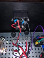
(Clearly I had trouble fitting my soldering tool into that area without melting the adjacent plastic).
Also, I have a small capacitor that ties from the plug prongs to the other set of prongs that then go to the toroid. I remember doing a lot of reading not only on this forum but elsewhere to be sure I knew what was going on first, and I know I wouldn’t have added that just out of my own head. But I was hoping someone could help me figure out why I did this.
As I’m looking at my point to point connectors, it looks and feels rather cheap to me and I don’t particularly trust it. I was wondering if anyone had recommendations for quality connectors for connecting the power to the transformer and the thermistors.
(Clearly I had trouble fitting my soldering tool into that area without melting the adjacent plastic).
Attachments

You could use blades, soldered to the wires, and plug them onto the switch instead of toasting the plastic...
Those blue capacitors are X and Y rated-caps (if all went right), installed to avoid turn-on-sparks.
The thermistors are there to help tackle inrush current on power-on. They have a higher resistance when they're cold, as they heat up resistance goes down to some small resistance and stay so while the amp is running. Inrush-current management easypeasy-way.
For how to connect all of it, best would be to look up a first-watt schematic, and eventually 6L6's F4 build guide where he tells it quite nicely...
TA....just to check, 24mF is microfarads or uF as we call it on this side of the pond, correct? So 24uF 35-50V and 0.1R 1W resistor?I wouldn’t change R9. R16 can be increased to the range you mentioned. The voltage on the Drain of Q1 would be increased along with a higher supply voltage.
My CRCRC values were 24mF/0.1R, 15mF/0.1R, 15mF.
Thanks
Thanks so much, that build guide is exactly what I needed!You could use blades, soldered to the wires, and plug them onto the switch instead of toasting the plastic...
Those blue capacitors are X and Y rated-caps (if all went right), installed to avoid turn-on-sparks.
The thermistors are there to help tackle inrush current on power-on. They have a higher resistance when they're cold, as they heat up resistance goes down to some small resistance and stay so while the amp is running. Inrush-current management easypeasy-way.
For how to connect all of it, best would be to look up a first-watt schematic, and eventually 6L6's F4 build guide where he tells it quite nicely...
TungstenAudio...is there a known schematic of the PS you suggest with the CRCRC arrangement to create the quasi dual-mono PSU for the ACA? Better yet, if there a known, (for purchase or gerbers) complete PS PCB that I can try with my ACA build?I agree with the recommendations above to increase the power supply capacitance. I have tried a number of different size capacitors using linear power supplies, and found that the larger ones definitely improve the sound of the amp, as well as reducing the hum. My preferred configuration came to be a 300VA transformer with 20V or 22V secondaries followed by a low Vf bridge rectifier, then a CRCRC capacitor set consisting of 36,000 uF, 1 Ohm, 15,000 uF, 0.11 Ohm, 15,000 uF. Both of the amps I built in the old Hafler chassis now use this style PSU.
Since the ACA is a single rail amp, the dual secondaries in a typical toroidal transformer can be used to make a quasi dual-mono PSU. If you prefer to use chokes, I would suggest placing them after the 36,000 uF bulk supply caps in each channel.
Since the modifications discussed in this thread result in increased bias current around 1.6A, the higher VA rating of the transformer is important to get good regulation. Following these guidelines, you should have an amp that sounds as good or better than a pair of bridged monoblock ACAs using the switching SMPS.
Is the rhthatcher W12 dual-mono (Etsy) what I'm looking for?
Thanks & cheers
Last edited:
So I got everything how I wanted it for my linear PSU, but when I turned it on, I got sparking at the DC output and some smoke (in the pictures, the back panel is off, but it was screwed on when I did this). The checks I had done beforehand were to verify the two sides of the diode, where I got 26V AC and 23 V DC, continuity checks from the diodes down to the DC output, with and without the drain resistor, continuity checks with one end on the chassis to everything that was supposed to be grounded, and resistance checks. The capacitors were too big to check for my multimeter.


Is the power supply working properly now, with no sparks?
I see that you connected the ground lift thermistor to the negative of the bridge rectifier. That is not the proper location for the thermistor. It should be connected to the output ground of the power supply, at the last capacitor, and then to the chassis ground.
What gauge are your wires? They look quite small diameter in your pictures.
I see that you twisted the transformer wires together. That is a good thing. However the other wires are not twisted together, which is not a good thing. The AC wires, live and neutral, from the IEC connector should be twisted together. The DC wires from the bridge rectifier to the power supply filter capacitors should be twisted together. The DC wires from the power supply output to the connector on the back of the chassis should be twisted together. This to minimize noise.
I’m honored to have your feedback, thank you so much! The power supply powers on with no sparks, but I haven’t actually hooked it up to power the ACA yet. The wires are 18AWG. I was just looking at the voltage rating when I bought them, but given your comment, I assume I should be using bigger wires. Also thank you for the feedback on the thermistor and twisting the wires. I’ll fix those things. I was confused about the correct placement of that thermistor.
The wires looked smaller in the pictures. 18AWG should work. Voltage rating is usually not an issue. Current carrying capacity needs to be taken into consideration. But 18AWG should be sufficient for your needs.
A question out of the blue, and I apologize if it's been asked before, possibly in the original ACA forum...if I use my B1K (Korg) preamp, which is phase inverting and required speaker leads being inverted out of one's amp, with my ACA, which phase inverts but is corrected for in the output wiring, I'm supposing I'll still have to invert my speaker leads out of the ACA to make everything right again 😉?
Cheers
Cheers
- Home
- Amplifiers
- Pass Labs
- ACA amp with premium parts