So the name of this thread is "Would a Single driver Manifold/MTB be better than Tapped Horn?"
The mayor advantage I see with the Manifold design over TH, is the ability to easily change port tunings, by replacing ports or just blocking them. Changing tuning is not possible with a TH, unless it has a large enough throat chamber, that the driver can be flipped around. Flipping a driver around is however not as easy as shoving a sock in a port.
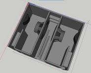
Also I have found that by making the horn section streight, I can achive better results and be able to install drivers, without the need for a access door.
Having a streight horn also makes construction super simple.
By making dual bins, it is possible to make a very small horn, but still be able to install drivers from the front.
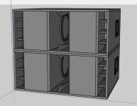
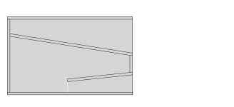
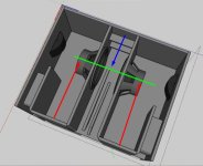
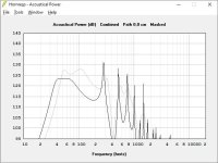
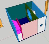
Here is a version 3.0 of my 212 bass bin:
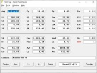
Drivers are 2x B&C 12NDL76
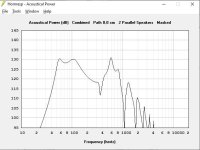
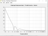
High tune: All 8 ports open
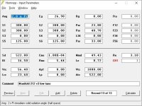
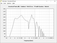
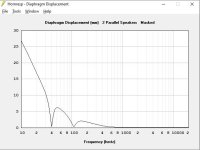
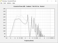
Low tune: 4 ports open, this gets you bass heads down to 40hz, but with significantly lower SPL.
A medium tune and a super low tune is also possible, but not included in the images.
The mayor advantage I see with the Manifold design over TH, is the ability to easily change port tunings, by replacing ports or just blocking them. Changing tuning is not possible with a TH, unless it has a large enough throat chamber, that the driver can be flipped around. Flipping a driver around is however not as easy as shoving a sock in a port.
Also I have found that by making the horn section streight, I can achive better results and be able to install drivers, without the need for a access door.
Having a streight horn also makes construction super simple.
By making dual bins, it is possible to make a very small horn, but still be able to install drivers from the front.
Here is a version 3.0 of my 212 bass bin:
Drivers are 2x B&C 12NDL76
High tune: All 8 ports open
Low tune: 4 ports open, this gets you bass heads down to 40hz, but with significantly lower SPL.
A medium tune and a super low tune is also possible, but not included in the images.
Attachments
-
 2x Manifold 212 v3.JPG43.2 KB · Views: 82
 -
 hornresp 540watts.JPG52.1 KB · Views: 84
 -
 hornresp low tune 360watts.JPG53.6 KB · Views: 85
 -
 Manifold 212 v3 inside.JPG97.3 KB · Views: 82
 -
 max SPL 540watts.JPG41.7 KB · Views: 82
 -
 max SPL displacement 540watts.JPG33.7 KB · Views: 80
 -
 max SPL low tune 360watts.JPG42.9 KB · Views: 80
 -
 max SPL displacement low tune 360watts.JPG33.8 KB · Views: 81

Also I have found that by making the horn section streight, I can achive better results and be able to install drivers, without the need for a access door.
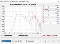
Looks like you are loosing some SPL close to 200Hz, try to change drive offset position close to S1, the total front horn length is the same but the driver place closer to dead end.
In addition to that, you can keep the vent straight, but probably you flare the front horn you can improve upper frequency range as well. Try to reduce S2 and increase S3 as much as possible and compare the SPL behavior.
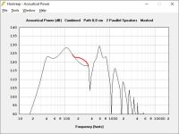
I moved them forward, because is removes the crazy third spike and deep valley, also seen in @Booger weldz post #244visually speaking, you can improve SPL in the area indicated by red line.
Also it very slightly increases SPL at around 100hz, which I care more about.
The final reason is simply that it makes driver installation easier.
Red is driver right at the back.
Thoughts?
Attachments
I moved them forward, because is removes the crazy third spike and deep valley, also seen in @Booger weldz post #244
Also it very slightly increases SPL at around 100hz, which I care more about.
The final reason is simply that it makes driver installation easier.
Sure, also try to evaluate S2 size, reducing S2 will provide additional improvement combined with increased S3.
So understand the effect of each variable over SPL you can better define your trade off case. Maybe the best results might be in the middle.
It worth to mention also that the lower frequency is defined by the rear chamber and vent, but the front chamber has a big impact in the upper range.
The option 1 and Option 2 in the image has exactly the same box volume but the ratio for the box are different:
Opt1 = depper lenght smaller horn mouth and bigger S1
Opt2 = taller box, bigger mouth and smaller S1
There are many variable you can play with to slowly optimizing the result in the direction you want.
With automation tool for freecad you can reduce a lot of time in this optimization routine.
Attachments
I moved them forward, because is removes the crazy third spike and deep valley, also seen in @Booger weldz post #244
Thoughts?
That sucker rings like crazy in my junk, good thinking if you find some affective acoustical shape/offset to avoid it
I wonder how much more affective you can manipulate this reflection (red) to work in your favor ?
I think the only one you’re describing to horn response is the one in the center section(blue)
I think the only one you’re describing to horn response is the one in the center section(blue)
Attachments
Last edited:
Reducing S2 and increasing S3 tunes the high frequency resonator and the kick bass 2nd spike up. Sure it ups the efficiency of that spike, but at the cost of efficiency at around 80hz, which is way more important in my opinion.Sure, also try to evaluate S2 size, reducing S2 will provide additional improvement combined with increased S3.
So understand the effect of each variable over SPL you can better define your trade off case. Maybe the best results might be in the middle.
I have been toying more with the idea of making a fully tuneable box, that can both function as a high SPL bass bin, but also as a lower SPL subwoofer.
So as I mentioned earlier, the low frequency chamber can be tuned down by blocking one or two of the ports. What if we can do the same thing with the high frequency resonator? Basically turning it into something that looks more like a BP6P box. I can't find a way to properly simulate this in hornresp. Horn 1 in the CH1 model doesn't have enough segments. When I try simming it as BP6P, it doesn't seem to work. Probably because I am doing something wrong.
Have any of you seen anything like this before? do you think it's an idea worth diving into?
Attachments
I can't find a way to properly simulate this in hornresp
CH1 I think can do the job for you the only difference is that you need to enable stepped segment, just double click on top of any segment (S1,S2,S3,S4) and they will change color from black to red, so you can have the last segment H3 to represent the hole in the new panel.
@LORDSANSUI you are a genius! It works like a treat. I am very happy with this concept. It allows very broad tuneability, for a wide range of drivers and circumstances.
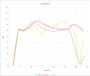
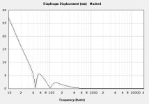
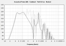
Here is a max SPL comparison. High tune without the adapters vs low tune with. The low tune is running significantly lower wattage to not exceed xmax.
Here is a max SPL comparison. High tune without the adapters vs low tune with. The low tune is running significantly lower wattage to not exceed xmax.
Attachments
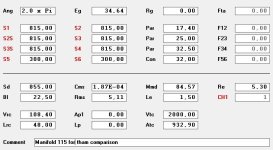
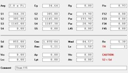
I did a quick sim of Martinsson's THAM, vs the best single driver manifold/BP6P, i could come up with.
Both use 15NDL76 driver and both have an internal volume of 180 litres.
I tried to match the upper and lower tuning frequencies of the manifold/BP6P as best I could.
All in all I think the results are very similar.
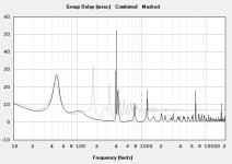
It seems the Manifold/BP6P gets a little more output, but the THAM has a little less delay. The THAM also looks a little more messy in the upper region outside of the band pass.
Also the Manifold/BP6P is very easy to design, as you can somewhat independantly tune the front and rear chambers and even re tune them after the build is complete by blocking ports or even flipping the driver around to change the volumetric ratio between the chambers. It is also easy to construct, as it requires no angled cuts.
This is in no way a critique of Martinsson's great design! Just fun to se how different systems compare.
Both use 15NDL76 driver and both have an internal volume of 180 litres.
I tried to match the upper and lower tuning frequencies of the manifold/BP6P as best I could.
All in all I think the results are very similar.
It seems the Manifold/BP6P gets a little more output, but the THAM has a little less delay. The THAM also looks a little more messy in the upper region outside of the band pass.
Also the Manifold/BP6P is very easy to design, as you can somewhat independantly tune the front and rear chambers and even re tune them after the build is complete by blocking ports or even flipping the driver around to change the volumetric ratio between the chambers. It is also easy to construct, as it requires no angled cuts.
This is in no way a critique of Martinsson's great design! Just fun to se how different systems compare.
Attachments
Could you share the sim and box dimensions used for the manifold in that comparison?
In addition to flexibility in tuning, the ability to shape the box is very handy too - low and long, high and short... Definitely a versatile design, I can't wait to share my exploration (but I'll save that until I'm ready to make sawdust)
In addition to flexibility in tuning, the ability to shape the box is very handy too - low and long, high and short... Definitely a versatile design, I can't wait to share my exploration (but I'll save that until I'm ready to make sawdust)
Sure!
I didn't do any box dimensions, but I know that this box is physically possible and should fit easily on a single sheet of ply.
The front chamber port is a bolt on panel, so the driver can be accessed and the port can be tuned by removing or replacing it. If you don't want to build a removable panel, you can tune the front chamber/horn to the same results by making it longer rather than porting it.
Attachments
I tried to match the upper and lower tuning frequencies of the manifold/BP6P as best I could
Did you tried to add Throat chamber + Throat Port to the model? in general it brings also additional improvement from the upper range. You need to model it using CH2, and the driver needs to be assembled with motor at rear chamber side.
Yes I have dabbled with this idea. As you say it does a great job of tidying up the out of bandpass mess, but it adds a great deal of complexity to the build, so I’m not sure if it is worth it. I use a DSP and crossover very steeply with the kick bin, so it doesn’t concern me much.
Sorry if this is too off topic!
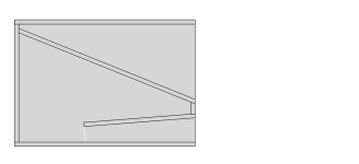
So I had this strange idea. What if, to massively over simplyfy things, we just put the driver in a pipe and put that in a box. This gives us a cylindrical horn and four triangular ports. Super simple. Five box sides, one pvc pipe, and some kind of circular baffle.
This seems too simple, but I can't see why it wouldn't work.
This also loads the driver evenly, compared the the offset driver plans discussed in this thread.
Any ideas how to sim this? as the ports feed into the horn like a paraflex, but unlike a paraflex, it has a rear chamber.
Here a picture of i kick bin idea. I just simmed it as a stepped horn, with a rear chamber port. Sims very nicely like that, but obviously not accurate.
Attachments

- Home
- Loudspeakers
- Subwoofers
- Case for Discussion - Would a Single driver Manifold/MTB be better than Tapped Horn?