That's standard binary from 0 to 5 . Either some 3/4bit BCD -> octal/decimal decoder + your diode logic, or some logic directly. Since designing the logic gates circuit can be quite complex, I would take the BCD -> decimal decoder. You may find some with non-inverted output to avoid the additional output invertors.
Or a trivial code in chinese mini arduino for 2 USD 🙂
Or a trivial code in chinese mini arduino for 2 USD 🙂
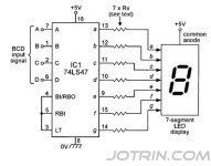
Same principle, but that circuit uses BCD to 7-segment decoder, a different IC. You would need BCD to decimal + the diodes. But I did not see any decoder with non-inverted output (while it may likely exist).
IMO the easiest way would be using the cheapest arduino nano with USB serial port for 3USD free shipping from Aliexpress, coding a trivial loop which reads the input pins and based on their value (a few ifs) setting the output M0/M1 pins. There are myriads of examples of such a simple loop online. Programming arduino is trivial with the Arduino IDE and a USB cable. You would just need to measure if 5V or 3.3V arduino were to be used. IMO this would be much easier and faster than hacking logical circuits and diodes.
IMO the easiest way would be using the cheapest arduino nano with USB serial port for 3USD free shipping from Aliexpress, coding a trivial loop which reads the input pins and based on their value (a few ifs) setting the output M0/M1 pins. There are myriads of examples of such a simple loop online. Programming arduino is trivial with the Arduino IDE and a USB cable. You would just need to measure if 5V or 3.3V arduino were to be used. IMO this would be much easier and faster than hacking logical circuits and diodes.
Last edited:
Arduino is an option but I'm worried about noise. The reason I didn't use the OLED display is that it raises 3rd order harmonic by ~5dB. I can't explain why does this happen.
Searching for a decoder I found the one attached. 8 non-inverting outputs -only 6 needed- and 3 inputs, exactly as many as needed. Do you think this would work? Or 4 inputs to 10 outputs -that is decimal isn't it- is mandatory?
Apologies for my naive questions.
Searching for a decoder I found the one attached. 8 non-inverting outputs -only 6 needed- and 3 inputs, exactly as many as needed. Do you think this would work? Or 4 inputs to 10 outputs -that is decimal isn't it- is mandatory?
Apologies for my naive questions.
Attachments

DIY soundcard V.2 build log entry #1.
Single PCB this time, I'm planning to keep it small... and simple. Almost eurocard dimensions -164x98mm- made to fit in the carcass of a Behringer UMC202HD. The proven circuit together with all possible upgrades occurred to me so far. Progress depends on time and budget. It won't be anytime soon, for sure. Wish me luck!
Single PCB this time, I'm planning to keep it small... and simple. Almost eurocard dimensions -164x98mm- made to fit in the carcass of a Behringer UMC202HD.
The proven circuit together with all possible upgrades occurred to me so far. Progress depends on time and budget. It won't be anytime soon, for sure. Wish me luck!Attachments

It's true that I don't remember ever using output "Right". However, I regularly use both inputs for impedance measurements with ARTA Limp and phase linearity with ARTA Steps in "Dual Channel" mode, that's why this button in the center of the soundcard. I have to find out how it's done in REW.
Sure, dual channel is needed, but "Channel 1" and "Channel 2" would make more sense to me than "left" and "right".
And there I was , assembling my new soundcard with great care to detail!

Yeah... But the DC converters were in a different mood. Those SIP4 boosters can be switching at frequencies over 200kHz but for the lower power at 1W. At 3W used here they were ringing at 50kHz spreading havoc all over the place. They were taking down -actually up and down repeatedly- the usb microcontroller. The DIYINHK module proved bullet proof! Unfortunately, I can't tell the same for a precious CS5381... By the time I figured all this, the board had ended up like this

I have already redesigned the PCB for new and better DC converters but before ordering, I will build a functional prototype on this one, no matter how it will look.
Now , the good news! I have verified communication between UCB and ADC/DAC! There's not much to show before the analog buffers are built, but the noise levels are promising!

Moreover, the CS5381 lends naturally M0/M1 combination to work directly with the DIYINHK module. It requires just two wires and auto sampling rate is a fact. No binary decoders, no diode networks. 👍

Yeah... But the DC converters were in a different mood. Those SIP4 boosters can be switching at frequencies over 200kHz but for the lower power at 1W. At 3W used here they were ringing at 50kHz spreading havoc all over the place. They were taking down -actually up and down repeatedly- the usb microcontroller. The DIYINHK module proved bullet proof! Unfortunately, I can't tell the same for a precious CS5381... By the time I figured all this, the board had ended up like this
I have already redesigned the PCB for new and better DC converters but before ordering, I will build a functional prototype on this one, no matter how it will look.
Now , the good news! I have verified communication between UCB and ADC/DAC! There's not much to show before the analog buffers are built, but the noise levels are promising!
Moreover, the CS5381 lends naturally M0/M1 combination to work directly with the DIYINHK module. It requires just two wires and auto sampling rate is a fact. No binary decoders, no diode networks. 👍
Last edited:
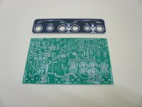
Currently, it looks like this.

Quick and dirty soldering, everything is on except the DC converters. The USB module will be sitting directly on pin headers. No more weird ribbons, only two cables for power supply and sampling rate. A missing copper trace from the negative rail regulator to the input opamps resulted to a fried positive regulator. 🤔 Fortunately, the opamps survived. The input stage is copied from the previous version and works as it should. The output stage on the other hand, is experimental and it doesn't beat the humble audio codec straight away. But it is designed to allow some trimming and I'm going to work on this now. Searching for DC converters, I found the XP Power IMM05 but using two of them for +/-15V makes price and space occupation similar to the Mean Well DKM10E-15 used already in the first version and it's great. I won't post schematics before I have the finals. I think I'm close.
Quick and dirty soldering, everything is on except the DC converters. The USB module will be sitting directly on pin headers. No more weird ribbons, only two cables for power supply and sampling rate. A missing copper trace from the negative rail regulator to the input opamps resulted to a fried positive regulator. 🤔 Fortunately, the opamps survived. The input stage is copied from the previous version and works as it should. The output stage on the other hand, is experimental and it doesn't beat the humble audio codec straight away. But it is designed to allow some trimming and I'm going to work on this now. Searching for DC converters, I found the XP Power IMM05 but using two of them for +/-15V makes price and space occupation similar to the Mean Well DKM10E-15 used already in the first version and it's great. I won't post schematics before I have the finals. I think I'm close.
Murphy's law evaluation platform. 😛

I had to put it aside for a while to recover. I made thoughts to trash it. Eventually, I transferred everything on an updated PCB.

Almost everything. You can see those caps to the right. And here you can see two opamps on the bottom side.

Here is the final assembly when the caps will find their place on the PCB and the bottom opamps get reversed... The PCB design program confused me and the pin out was mirrored.

For now, the opamps are fixed like this....

It comes to life but not in a consistent way. Not all input/outputs work the same. The digital converters seem intact but the opamps -all of them- suffered a lot during the past winter. Waiting for new replacements, I can post the best available loopback for the time being. Right output to left input. Also not perfect but gives an impression of its potential.

I had to put it aside for a while to recover. I made thoughts to trash it. Eventually, I transferred everything on an updated PCB.
Almost everything. You can see those caps to the right. And here you can see two opamps on the bottom side.
Here is the final assembly when the caps will find their place on the PCB and the bottom opamps get reversed...
The PCB design program confused me and the pin out was mirrored.For now, the opamps are fixed like this....
It comes to life but not in a consistent way. Not all input/outputs work the same. The digital converters seem intact but the opamps -all of them- suffered a lot during the past winter. Waiting for new replacements, I can post the best available loopback for the time being. Right output to left input. Also not perfect but gives an impression of its potential.
The only gear around me here that is not diyed is the oscilloscope and the soundcard.
It's time to 50% change this.
Kostas, I have tested your previous version of the sound card and I was very satisfied with the test results and it's functionality.
Do you accept orders for a kit of this version?😀
George
It's time to 50% change this.
Kostas, I have tested your previous version of the sound card and I was very satisfied with the test results and it's functionality.
Do you accept orders for a kit of this version?😀
George
I abandoned the idea of a diy oscilloscope since those tiny microprocessors came up. But I can help with a diy soundcard. I will post complete schematics and gerber files when it's fully debugged. Unlike the first version, this one is relatively easy to build and cheaper.
So, today I have it in working order(?) and proceeded to get some basic loopback measurements. Started with ARTA/Win7 which allows for a more "manual" calibration, at least to my understanding. I could take signal at full scale but the result doesn't even beat the first version. Disregard the 50Hz peak, it's because it was lying naked on the bench.

ARTA seems more straightforward to me, it's short of "what you see", no tricks. REW on the other hand is "what you read" but in my opinion it takes decisions in the backround. Calibration in Linux/REW requires rebooting but it's rewarding in the end. It is possible to reach full scale but the figures are mediocre...

I've been chasing sweet spots and settled to this

So, now I think I can post schematics and set targets for final possible upgrades.
The input stage is essentially the same with the first version. The incandescent lamps are substituted for jfet current limiters and the balanced/unbalanced switch is omitted as it didn't make any sense. Also, there is not a high gain preamp any more. Notch filters/LNA should be external. Actually, I had included that in the first version to use it with an inductive probe for EMI detection but the "Humboy" solved that in the best way. https://www.diyaudio.com/community/...r-hum-problems-the-humboy.378178/post-6815018 . Together with auto sampling rate it makes a total of three switches eliminated.

The output stage is completely different with PCM1794. I/V conversion is copied from datasheet but then it doesn't go summing the balanced outputs and restore with balanced drivers. Instead, the input buffer is applied once more. OPA1632 can drive usual loads and it's immune to short circuits. Just no DC protection but there wasn't any in the first version too. The bal/unbal switch is necessary here. One first problem: 1μ caps and 10k pot result to an early roll off. I was hopping to get away because there is no room for bigger quality caps, so the pot value has to increase.


The power supply starts with an external 5V/1,5A -better 2A- and after basic TVS and resettable fuse protection it splits to 3,3V regulator for the usb module -LD33V3 low drop with different pin out from LM78XX- and to isolated +/-15V SMPS. Then through RC filters is sent to local regulators. All regulators are plain linear three terminal. Results indicate that may or may not compromise performance. I'm still confident about the opamps' PSRR. I wonder if there would be any improvement replacing those at the analog supply of the digital converters.

And this is how it looks like. Top cover is photshopped to erase evidence of its origins. 🙂


ARTA seems more straightforward to me, it's short of "what you see", no tricks. REW on the other hand is "what you read" but in my opinion it takes decisions in the backround. Calibration in Linux/REW requires rebooting but it's rewarding in the end. It is possible to reach full scale but the figures are mediocre...
I've been chasing sweet spots and settled to this
So, now I think I can post schematics and set targets for final possible upgrades.
The input stage is essentially the same with the first version. The incandescent lamps are substituted for jfet current limiters and the balanced/unbalanced switch is omitted as it didn't make any sense. Also, there is not a high gain preamp any more. Notch filters/LNA should be external. Actually, I had included that in the first version to use it with an inductive probe for EMI detection but the "Humboy" solved that in the best way. https://www.diyaudio.com/community/...r-hum-problems-the-humboy.378178/post-6815018 . Together with auto sampling rate it makes a total of three switches eliminated.
The output stage is completely different with PCM1794. I/V conversion is copied from datasheet but then it doesn't go summing the balanced outputs and restore with balanced drivers. Instead, the input buffer is applied once more. OPA1632 can drive usual loads and it's immune to short circuits. Just no DC protection but there wasn't any in the first version too. The bal/unbal switch is necessary here. One first problem: 1μ caps and 10k pot result to an early roll off. I was hopping to get away because there is no room for bigger quality caps, so the pot value has to increase.
The power supply starts with an external 5V/1,5A -better 2A- and after basic TVS and resettable fuse protection it splits to 3,3V regulator for the usb module -LD33V3 low drop with different pin out from LM78XX- and to isolated +/-15V SMPS. Then through RC filters is sent to local regulators. All regulators are plain linear three terminal. Results indicate that may or may not compromise performance. I'm still confident about the opamps' PSRR. I wonder if there would be any improvement replacing those at the analog supply of the digital converters.
And this is how it looks like. Top cover is photshopped to erase evidence of its origins. 🙂
Last edited:
Nice!
I wonder why you used adjustable potentiometers for input attenuation instead of a switch with fixed resistors. A set of fixed resistors would (i) allow better symmetry in the balanced input, and (ii) make life easy to reproduce accurate attenuator settings between different measurements.
I wonder why you used adjustable potentiometers for input attenuation instead of a switch with fixed resistors. A set of fixed resistors would (i) allow better symmetry in the balanced input, and (ii) make life easy to reproduce accurate attenuator settings between different measurements.
- Home
- Design & Build
- Equipment & Tools
- DIY soundcard intended for measuring amplifiers