See my latest design in the PA forum. That uses a TPU rim that I glue the plate onto. Seems like results are much better than my efforts at clamping. They sound tighter than my clamped plates, probably since I reduced the dimension of the plate, and the TPU frame seems to dampen quite well but if feels like the plates struggle less and have better response down to 100Hz. Should have measurements and more details on the design soon.I know people often use weatherstrip foam as edge damping but has anyone tried a stretchy fabric surround? I imagine it would need the exciter to be supported.
My thinking is the piston action in the low frequency range would be less restrained. I guess it may need some edge damping or else it could be like a free plate and ring.

I have a question for builders here. Have any of you experimented with modifying any of the Dayton Audio exciters which use either the triple outrigger feet or the quad out rigger feet and have cut the feet off mounting them using only the adhesive on the lip of the voice coil? If so could you comment on you findings, better worse or just different? I am guessing but it would seem these feet will provide an increase of coupling area between the driver and the panel. A similar effect could be to use a standard coin type exciter and mounting it to a reinforced section of the panel say a 2-3 inch circle coated with a full strength coat of PVA adhesive. While not exactly the same thing it is similar in that this helps the driver to push and pull more efficiently on a larger area of the diaphragm. thought and comments both pro or con are most welcome. Thanks.
Not tested but what I recall from my (full) reading of this thread and of the audio circle one is a general recommendation to not use the exciters with legs. I am not able to give a link to a post showing why...I think somewhere Steve explained how he dismantled his exciters.I have a question for builders here. Have any of you experimented with modifying any of the Dayton Audio exciters which use either the triple outrigger feet or the quad out rigger feet and have cut the feet off mounting them using only the adhesive on the lip of the voice coil? If so could you comment on you findings, better worse or just different? I am guessing but it would seem these feet will provide an increase of coupling area between the driver and the panel. A similar effect could be to use a standard coin type exciter and mounting it to a reinforced section of the panel say a 2-3 inch circle coated with a full strength coat of PVA adhesive. While not exactly the same thing it is similar in that this helps the driver to push and pull more efficiently on a larger area of the diaphragm. thought and comments both pro or con are most welcome. Thanks.
The legs are linked to the exciter body so they create in my opinion a kind of a fix point closed to the voice coil. It is a solution to the problem of the magnet fixation but it probably changes a lot the panel behavior with as additional parameter the local mass added and the legs stiffness.
Hello moray.
All of my exciters I purchased over 15 years ago had the frogs feet( as they called them) which I had to cut off, including the casing.
They produced too much noise and was transferring that noise to the panel material.
I have had bad experiences with plastic encased exciters such as the hdn8, the exciter body should be as silent as possible and not be attached to the panel material, including the plastic or metal spider suspension which is attached to the coil former.
The 10watt Xcite xt19-4 has a plastic casing, which I am a little unsure of, but I am intrigued by it's long term power rating of 20watts ?
Has anyone had experience of this exciter and does it live up to its specification?
Steve.
thank you for this heads up information of which I have made note!All of my exciters I purchased over 15 years ago had the frogs feet( as they called them) which I had to cut off, including the casing.
They produced too much noise and was transferring that noise to the panel material.
I have had bad experiences with plastic encased exciters such as the hdn8, the exciter body should be as silent as possible and not be attached to the panel material, including the plastic or metal spider suspension which is attached to the coil former.
I ahve a pair of theese DML like speakers in the basement. They sound horrible beacause of the styrofoam frame amd bracing on the back. I will dig them up an cut the frame and brace off and see how they sound.
If I remember correctly the panel is EPS with a centerdome made of some plastic metal foil mix.
Hello Pepe.
I have never seen this type of antique panel before.
It looks like a collectors item to me.
If you cut off the frame and brace that is supporting the large magnet, the heavy magnet will probably just fall off.
The eps looks like it is a very high density that has been moulded , similar to a chiller box.
Not the best of sounding materials I believe , from my experience with using chiller boxes.
Steve.
Thank you Spedge for the reply.
Yes I think they are of QuietComfort high density.
Mine are NOS items in original box. Poctures are borrowed from the web.
I Will dig mine out during the week end and take a closer loook
Yes I think they are of QuietComfort high density.
Mine are NOS items in original box. Poctures are borrowed from the web.
I Will dig mine out during the week end and take a closer loook
Pepe.
Were these panels supposed to go in wall or be mounted in your own box?
They use damping rings filled with brown glue (can't remember the name of the glue at the moment 🙄) also they are using a dome tweeter in the central area.
Interesting.
Were they from the 70s?
Who made them ?
Steve.
Were these panels supposed to go in wall or be mounted in your own box?
They use damping rings filled with brown glue (can't remember the name of the glue at the moment 🙄) also they are using a dome tweeter in the central area.
Interesting.
Were they from the 70s?
Who made them ?
Steve.
J have no idea how they where ment to be mounted. I bought them a few years ago just for fun and they where really old (70's) but NOS when I bought them.
It's actually a metal dustcap and not a dome tweeter.
I will dig the boxes out tomorrow and see who te manufcterer where of theese horrible sounding panels. Mine dousnt have the glue in the ribs if memory serves me correct.
It's actually a metal dustcap and not a dome tweeter.
I will dig the boxes out tomorrow and see who te manufcterer where of theese horrible sounding panels. Mine dousnt have the glue in the ribs if memory serves me correct.
Pepe.
The metal dust cap will act like a tweeter radiating hf from the central voice coil.
If it was designed to go in a box , it might sound a little lacking in low frequencies and because of the very high density eps it might found a little harsh, not a good combination I think.
Steve.
The metal dust cap will act like a tweeter radiating hf from the central voice coil.
If it was designed to go in a box , it might sound a little lacking in low frequencies and because of the very high density eps it might found a little harsh, not a good combination I think.
Steve.
I don't agree with you that a sub can't extend up to 300Hz.I would not x-over at 300Hz for a couple of reasons. First of all I really like the sound of the plates from 120Hz upwards, and secondly it is hard for a sub to cover that high
In fact, 300Hz is exactly where I chose to crossover with my Hybrid design.
@Audio>X I haven't said that a sub can't extend that high, and that could be what is best for your system.
I would say it is a strange starting point though, and systems using a x-over that high are rare for a reason. At 300Hz the waveforms are directional, so no longer acting like a sub, and it is asking a lot from an element to reproduce more than 3 octaves efficiently. And our hearing is more sensitive in that range, so placing x-over there will interfere more. If you can place the subs so stereo image remains intact and don't expect the sub to cover below 40-50Hz it might work ok.
How come you selected such a high x-over? You don't like the sound of DML in the low mid? They lack sensitivity or power in that range?
I think this is worth playing with. I did try something similar, but not quite what you are suggesting. In my experiment, rather than the stretchy surround, I used my Poron foam, except rather than have the foam sandwiched between the panel and the frame, I used a frame that was about 1/4" larger than the panel, used the foam to bridge the gap between the panel and the frame. Overall, I do like the sound of this panel. This arrangement gave me decent bass down to 50 Hz, but left a big gap between about 70 and 130 Hz. But that doesn't mean that the same would be true of a better execution of the concept. This version provided great damping, and no ringing. I'm not sure how a really elastic surround with less damping would work, but it might.I know people often use weatherstrip foam as edge damping but has anyone tried a stretchy fabric surround? I imagine it would need the exciter to be supported.
My thinking is the piston action in the low frequency range would be less restrained. I guess it may need some edge damping or else it could be like a free plate and ring.
Eric

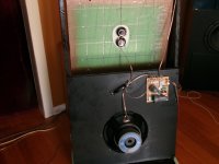
My hybrid DML speaker is an 'all in one' integral design, without the sub being in a different room location. It incorporates sub + DML + tweeter.How come you selected such a high x-over? You don't like the sound of DML in the low mid? They lack sensitivity or power in that range?
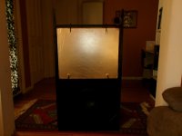
Because my sub is of 'open baffle' design, the speaker is large in size > required for the sub baffle. Correspondingly, my DML's are 500mm x 600mm.
I found the DML's to have excessive output in the 300 to 400Hz range > SO, I designed the crossover to 'roll off' and reduce in this region.
This essentially dictated where I would crossover to the sub. Also, the design is made for high power & volume levels. 2x exciters = 80 WRMS.
The following pictures will show how the DML's basically 'float' above the 12" subs. [ I didn't find 'summing problems' or directionality of the subs ]
https://www.diyaudio.com/community/...f236fc9cf1cc900f83e8fc17c.jpg?hash=9ZuTXyNvyc
https://www.diyaudio.com/community/...60a447f3362654fd805c13126.jpg?hash=qgYKBgpEfz
https://www.diyaudio.com/community/attachments/100_0021-jpg.1291582/
https://www.diyaudio.com/community/attachments/100_0013-copy-jpg.1291581/
Last edited:
Hello Eric,I used my Poron foam, except rather than have the foam sandwiched between the panel and the frame, I used a frame that was about 1/4" larger than the panel, used the foam to bridge the gap between the panel and the frame.
Is the poron foam the dark grey horizontal and vertical rectangles? On the picture there is a darker area in the upper suspension area which I suppose is a shadow. Which width are the poron foam parts?
Christian
The overlap area of the panel and the poron foam may act as a constraint damping layer area (?). If it is like that, the overlapping width is a parameter to adjust the damping.This version provided great damping, and no ringing.
Hi Eric,
Thanks for the image, I have tried a similar surround suspension with 40mm wide epdm foam tape, it worked well as you experienced. Best bass I have had too, your dip between 70-130hz may have been exciter placement related, I remember having a strong 50-60hz then a dip below 100hz somewhere. I can't find the measurement. This was with a 2/5-3/5 placement.
I will re-measure the ones I am using in my workshop as they have the foam tape surround. I tried a central and 3/5 placement for these after watching Ben Zenkler's video on exciter placement and had better low end I think.
I will also try the fabric surround idea to see if it has legs.
Christian,Is the poron foam the dark grey horizontal and vertical rectangles? On the picture there is a darker area in the upper suspension area which I suppose is a shadow. Which width are the poron foam parts?
I see now that the shadows make the original picture a little confusing. Maybe these images make things clearer. The foam is 38 mm wide and 6 mm thick.


I'm more inclined to think that the damping mainly comes from the part of the foam that bridges the 3 mm gap between the edge of the panel and the start of the frame. That's the region of the foam that will have the most deformation, and hence the most opportunity for damping. I think the overlapping width is mainly just "going for the ride" along with the panel. I chose to have about the same overlap on both the frame and panel simply to provide the same strength of connection on both places.The overlap area of the panel and the poron foam may act as a constraint damping layer area (?). If it is like that, the overlapping width is a parameter to adjust the damping.
Eric
- Home
- Loudspeakers
- Full Range
- A Study of DMLs as a Full Range Speaker