What are you going to be selling in the store John?
I'd like to sell the raw waveguides for people without access to 3D printers, but I've also had some interest from people for the full-range active variant I've built. So will be doing a very small production run of those.

So I'm going to attempt a traditional conical MEH version with the same coverage angle/ports to use as a control as well as a 4-point star version.
I would love to see that. My assumtion is that if the port placement does not interfere much worse, the regular Tritonia-style/PT-Waveguide should be supperior.
It is Erin, yes. I believe it's on the stand today, so should have some measurement data to share shortly.
This must be the most honest and thoughtful thread I have read about MEH 🙂
First results. The on-axis response needs a little fixing, so posting the spinorama after we get a new DSP file loaded and flatten the response. I think the input PEQ filters might have been disabled by me by accident in the hypex software.


So a few things that stand out to me:
So a few things that stand out to me:
- The narrowing at 1kHz is interesting. I imagine this is either waistbanding from the horn geometry or it's something crossover related as 1kHz is the xo frequency. Right now I'm using 4th order slopes, but may have some flexibility to go steeper or shallower.
- doesn't seem like the asymmetrical port on the side of the enclosure is having any negative impacts to the polars being lopsided or uneven, which is good. I think a couple of people had pointed that out to me as a point of concern previously.
- narrows a lot above 10kHz, slightly disappointed by that but also not surprised as my measurement setup doesn't really get accurate data that high. I'm curious since the "knuckles" are positioned on the horizontal and vertical axes if a 10° inclination (or roll?) would show that they're wider that high up.
Attachments
Personally, I’m curious how audible these little diffraction elements are. Once we get the proper DSP setting I will run the impulse response through a convolver and see if there’s a noticeable difference in an AB test (assuming otherwise linear on-axis response). Might even dump the files here if others want to do a ABX test via foobar or otherwise.
I’m excited to see where this goes.
I’m excited to see where this goes.
Other notes: as John said, it’s nice to see that
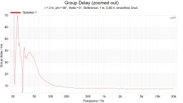
a) the port doesn’t create any irregularities; evidenced by the symmetry of the horizontal contour. If the port were resonating you’d see the side-bias here and what little I do see is me looking hard for any inconsistencies. The group delay also shows no large differences through the midrange which is another sign of no port or enclosure resonance.
b) the directivity is damn near perfect. I haven’t seen sound power this linear since I reviewed the KEF Blade 2 Meta (below). This means any issues in linearity can be resolved via EQ or if one wants to add “flavor” this can easily be done without worrying about the early reflections not matching the direct sound in a room.
KEF Blade 2 Meta below. Amazing performance from a passive speaker. Albeit at $30k/pair.
https://www.erinsaudiocorner.com/loudspeakers/kef_blade2_meta/
First results.
Is this the same box as measured at https://www.jwsound.live/blog/bhv2rxe7yc1zedlaj0wujc9zk81amb ?
Is this the same box as measured at https://www.jwsound.live/blog/bhv2rxe7yc1zedlaj0wujc9zk81amb ?
It is yes.
Just for visual comparison's sake, I loaded the Klippel files into vituixcad to see how they look against what I measured using the ground plane + gated method on a turntable. Part of getting this speaker measured was to identify deficiencies in my measuring techniques. Other than the >10kHz discrepancy, I do think that the general shape of the polars does seem to agree.
Ignore below ~80Hz obviously.
DIY Turntable Horizontal:
Klippel Horizontal:
DIY Turntable Vertical:
Klippel Vertical:
Glad to see nearly zero port compression up to 120 dB!It is yes.
And no (or very low) port resonances:
Thanks for posting the measurements!the port doesn’t create any irregularities;
Yeah very happy with the port's performance. Thank you for sharing the tool you built @stv!
THe port compression test I did was with a LR24 80Hz HPF engaged, so it might look different with with the 43Hz BU4 HPF that's used when in full range mode.
I think I need to recreate that graph with the DSP in full range mode to see what port compression looks like around Fb. Albeit probably not to 120dB lol.
It is yes.
Just for visual comparison's sake, I loaded the Klippel files into vituixcad to see how they look against what I measured using the ground plane + gated method on a turntable. Part of getting this speaker measured was to identify deficiencies in my measuring techniques.
Do you have a picture and/or description of your physical setup for directivity measurements? (Edit: ) Was the center of the box (depth of the HF driver) flush with the turn axis of the turntable, or was the baffle (front of the box) flush with the turn axis?
What was your measurement distance? And what was the distance the NFS was set to to calculate its far field response?
By default, the NFS operates under the CEA-2034 standard which is measure at 2m, reference to 1m. 2.83v for passive speaker.
Of course, I can change this in the software easily. I’ve got a pair right now that require 4m for proper summation so I’m providing both distances (2m and 4m), but both referenced to 2.83v/1m.
Of course, I can change this in the software easily. I’ve got a pair right now that require 4m for proper summation so I’m providing both distances (2m and 4m), but both referenced to 2.83v/1m.
Do you have a picture and/or description of your physical setup for directivity measurements? (Edit: ) Was the center of the box (depth of the HF driver) flush with the turn axis of the turntable, or was the baffle (front of the box) flush with the turn axis?
What was your measurement distance? And what was the distance the NFS was set to to calculate its far field response?
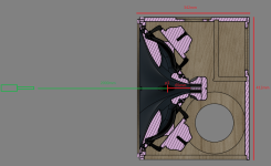
I use this guide for the gated measurements with the speaker on a tripod elevated about 2.2 meters from the ground and the microphone at a 1.5 meter distance from point p1 shown below. The box is rotated around p1 for taking off-axis measurements.
Instead of using the guide's nearfield bass instructions, I move the speaker out to a large parking lot and take ground plane measurements at 1.5 meters. This is done with tilting the speaker down and using a digital level to ensure that the angle places the microphone on-axis. I merge the ground plane responses with the gated responses at 400Hz in vituixCAD.
This is all done with a Focusrite 2i2 2nd gen interface and EMX-7150 mic.
As far as how confident I am that the microphone is precisely on-axis during the gated measurements - not very. I try to line it up as close as I can, but the wavelengths are very short in the top octave, so I think small errors of a few cm could likely result in the the previously mentioned discrepancies - especially given the complex geometry of this waveguide. Again though, I'm not going to stress too much about getting accurate data that high up with my measurement process as the Klippel is far more reliable and takes the guesswork out of the equation.
Attachments
The reference point for the NFS would be the front, I assume, as opposed to your offset point. Some slight vertical misalignment on the manual measurement might also come into play; horizontal, not so much, as that would show in left-right deviance in the chart.
Fwiw, I have such a comparison (automatic turntable vs. NFS) behind me, and the results matched very well up to 20 kHz - so this is why I was surprised by this drastic difference here in the VHF region and was trying to help diagnose it.
Erin, thanks for the info, and in general, for helping and supplying the data. If it's not too much of a burden, can you post the horizontal directivity graphs for 1, 2, and 4m distance? There might still be a non-negligible difference.
And, unrelated to that, would it be possible to also see a decay chart for this speaker, ARTA style, like you do it for your speaker reviews on your website? galucha has already posted one on his website, but a gated one, which would hide / mask resonances at anything less than the high frequency region. There are few to no complete decay charts of MEHs out there, so it would be quite valuable to see.
@bikinpunk; are you going t do a video about the Solana? I’ll be very interested to hear your subjective impressions as well as the objective measurements.
honestly, I think this narrowing pattern / amount of beaming is very inconvenient to illuminate an area evenly. I hate it when the PA dictates where I would like to be on the dance floor. I would thus go for a complete rework of the waveguide.
Well it wouldn't be the first time I've pivoted for a redesign on this project if it comes to that.honestly, I think this narrowing pattern / amount of beaming is very inconvenient to illuminate an area evenly. I hate it when the PA dictates where I would like to be on the dance floor. I would thus go for a complete rework of the waveguide.
On one hand, I do have a couple of waveguide variations in the build queue to test, but on the other I do think i'll be doing some more investigation on the top end results to understand what might be happening. I think I'll set up a measurement rig as shown below and vary the elevation of the mic over several positions to see the effect in the HF.
My hypothesis is that the polars in the top octave might be wider at elevations corresponding where the valleys are in the waveguide. The practical/subjective perception implications of this is unclear at this point if true though.
- Home
- Loudspeakers
- Multi-Way
- Portable Battery Powered MEH Build