The grid resistor on the second 12AX7 is also 1k.
I know there are some pretty unconventional component values there, such as the 10M resistor, but that's Croft.
I know there are some pretty unconventional component values there, such as the 10M resistor, but that's Croft.
I have a couple of questions, my integrated phono looks a little different:

I tried to work out the schematic: the section after the volume pot looks identical to @Ejam schematic in #30 (except for the reversed diodes, and mine has P5NK50ZFP in place where he has P9NK50ZFP). But the RIAA network looks different: please comment and let me know what you think. Other questions that I have: do you also have the little circuit right at the speaker bindings?

I don't understand how it works, and I wonder why the 2200uF cap seems to be connected reverse biased...? And what about the LM317 circuit: does that look identical to yours?

I tried to work out the schematic: the section after the volume pot looks identical to @Ejam schematic in #30 (except for the reversed diodes, and mine has P5NK50ZFP in place where he has P9NK50ZFP). But the RIAA network looks different: please comment and let me know what you think. Other questions that I have: do you also have the little circuit right at the speaker bindings?
I don't understand how it works, and I wonder why the 2200uF cap seems to be connected reverse biased...? And what about the LM317 circuit: does that look identical to yours?
Attachments

Another question: how to adjust bias of the output mosfets? I have 124mA flowing from the positive rail into the output stage and 1V between the gates of the 2 mosfets. Is that OK?
Found a small mistake in my schematic in #43: the triac has MT2 connected to GND, MT1 is goes to the speaker terminal.
There is a tape out buffer added by Croft himself to a 25, see here. I might be interested to add this to my preamp and tried to create a schematic from the pictures posted there:

Does it make sense? Looks like a simplified version of the line stage in my super micro...
There is a tape out buffer added by Croft himself to a 25, see here. I might be interested to add this to my preamp and tried to create a schematic from the pictures posted there:
Does it make sense? Looks like a simplified version of the line stage in my super micro...
First thank you for all schematic creatings.
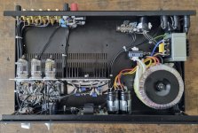
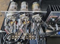
The transformer for the tube voltages (go to image No 4, 9 and 10 in post #14) seems to be faulty and the reason for a too loud hum in the speakers.
The owner (of the device from post #14) note a thermal issue on this small transformer - already without load (i.e. with disconnect rectifier diodes):
40°C after 7-10 minutes after switch on and above 50°C after 20 minutes.
The measured AC voltages under this conditions are 207VAC and 15VAC.
Who can post this values for the power amplifier (series 7) with transformer in correct working condition ?
Where can the owner order a new transformer ?
Thank you very much for an advice.
I have 250V and 15V, but my amp is an integrated with phono stage. These small transformers can get hot when overloaded, but 70°C after 1 hour under full load should be OK. 50°C after 20 minutes without any load sounds a bit strange to me. Also in #30 @Ejam shows 320V in his schematic: if that is correct, your transformer is probably smoked. Let me know if it helps and I can open up my amp again to measure the temperature of the transformer under load. You can ask input audio for a replacement transformer, or custom order it from one of the Chinese makers on Ebay, or ask one of the European companies to make you one. I saw in one of Croft amplifiers that he used a transformer by Trans-Tronic:

Have a look at picture 14 in #14: there is a sticker on the transformer!!! Ask your friend to read what the sticker says and you might be able to get the replacement transformer. The sticker looks similar to the one in #47.
good advice - thank you. He must remove the capacitor because the sticker isn't on top as to see in the image from post #47
Not necessary: just bend it up a little bit and use a dentists mirror to make a picture with the phone.
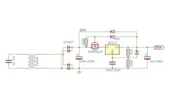
The topology of the serial regulator for the anode supply voltage from schematic in post #43 isn't often to find.
I guess, there is a certainly naming for this kind of regulation. In post #2 under
Creating High Voltage for Tube Power Supply: Ser./Shunt Regulator and Passive RC Filter Chain with Choke/Inductor; Pros and Cons
I ask therefore. In the attachment there you will find three other examples for regulation in this kind.
The regulator for anode voltage is a so called Maida style regulator - the paper from National Semiconductor so as some URL's are to find in post #7 under
Creating High Voltage for Tube Power Supply: Ser./Shunt Regulator and Passive RC Filter Chain with Choke/Inductor; Pros and Cons
Creating High Voltage for Tube Power Supply: Ser./Shunt Regulator and Passive RC Filter Chain with Choke/Inductor; Pros and Cons
Yesterday the owner get a new transformer (exact the same model) and he tell me, that the DC resistor value of the secundary winding for the anode voltage is approximately 700 ohms at the new transformer and only 500 ohms at the old one. Now he will measure the AC and DC voltages both with old and new transformer - in a first step only AC voltages without connected rectifier diodes.First thank you for all schematic creatings.
The transformer for the tube voltages (go to image No 4, 9 and 10 in post #14) seems to be faulty and the reason for a too loud hum in the speakers.
The owner (of the device from post #14) note a thermal issue on this small transformer - already without load (i.e. with disconnect rectifier diodes):
40°C after 7-10 minutes after switch on and above 50°C after 20 minutes.
The measured AC voltages under this conditions are 207VAC and 15VAC.
Who can post this values for the power amplifier (series 7) with transformer in correct working condition ?
Where can the owner order a new transformer ?
Thank you very much for an advice.
Maybe the fault on the old transformer is a consequence due the fault in the serial regulator for anode voltage.
In Austria - the formerly distributor from the days, where Croft still exist - go to
https://www.georgruppert.at/croft-acoustics-in-leider-geschichte/
https://www.georgruppert.at/croft-acoustics-in-leider-geschichte/
I found a small mistake in the regulator circuit...
Another mistake: the line stage uses ECC83, not ECC82. Here the final schematic:

according the pdf attachment from Germans magazine "LP" was 2016 the German distributor this company :In Austria - the formerly distributor from the days, where Croft still exist - go to
https://www.georgruppert.at/croft-acoustics-in-leider-geschichte/
input audio HiFi-Vertrieb, Bernd Hömke
Ofeld 15 D-24214 Gettorf
Tel.: +49 (0)4346 – 60 06 01
Fax: +49 (0)4346 – 60 06 03
E-Mail: b.hoemke@inputaudio.de
maybe you can order also here the transformer.
Attachments
The new transformer works fine without thermal runaway (10 degrees above ambient) and without any audible hum from the loudspeakers (provide much higher value for anode voltage). Values for the voltages of the faulty old and new transformer I will post in the next days.Yesterday the owner get a new transformer (exact the same model) and he tell me, that the DC resistor value of the secundary winding for the anode voltage is approximately 700 ohms at the new transformer and only 500 ohms at the old one. Now he will measure the AC and DC voltages both with old and new transformer - in a first step only AC voltages without connected rectifier diodes.
Maybe the fault on the old transformer is a consequence due the fault in the serial regulator for anode voltage.
There is a tape out buffer added by Croft himself to a 25, see here.
Found more pictures online: the tape out buffer is the same circuit as the low gain line stage in the 25 / 25R. The pictures of the tape out buffer:


- Home
- Amplifiers
- Tubes / Valves
- Croft Series 7