Hi Ejam,
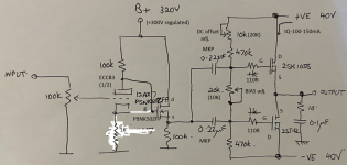
Thank you for the schematic. I think it's close, but I think there must be an error in the front end as drawn. As far as I have been able to determine from available pictures the ECC83 has an 1K resistor in the cathode and the gate of the mosfet is connected to the anode of ECC83.
Also, according to your schematic the source follower mosfet seems to be PSNK50FZP, but I guess the "S" is actually a "9" so it must be P9NK50ZFP, which seems plausible. I would have expected a mosfet with somewhat lower crss.
Hi geoturbo,
That's actually a good suggestion. But does that device exist? Google seems not to suggest it.
That's actually a good suggestion. But does that device exist? Google seems not to suggest it.
Thank you very much.The Croft Series 7 output stage is attached. No feedback. Note the 100k resistors for anode and source. Pretty simple, but keep in mind that Glenn Croft often slightly varied the circuit. Hope that helps.
View attachment 1439841
Who can upload the schematic from the version of Holger Stein (Steinmusic), mentioned in the German magazine Klang&Ton; 3/1993 ?
His old website are mentioned in post #12.
@mkc Please take it with a grain of salt, could this be it:
https://www.alldatasheet.com/html-pdf/168931/STMICROELECTRONICS/P5NK50ZFP/1946/1/P5NK50ZFP.html
Similar part no appears to be avail from mouser and usual suspects
https://www.alldatasheet.com/html-pdf/168931/STMICROELECTRONICS/P5NK50ZFP/1946/1/P5NK50ZFP.html
Similar part no appears to be avail from mouser and usual suspects
Interesting how this thread suddenly came alive!
I agree with banat: The gate of the Mosfet should definitely go to the plate.
As for the source resistor: I think 100K is probably too much. My experiments and measurements showed that around 15K was a viable compromise between wasted heat in the resistor and optimal(ly low) THD. This resistor provided some 10-15mA through the source follower. The output devices must still be fed from a low impedance source.

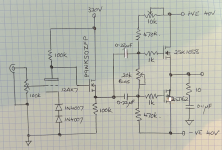
Sorry guys, too little sleep nowadays, two mistakes crept in, humblest apologies. To the corrections, yes it is a P9NK50ZFP. Second, the 12AX7's anode is connect to the gate, not the cathode to gate. Lastly, I checked my amp with Banat's diagram, the 12AX7 has two diodes in series to bias the cathode, not a resistor. The gate resistors are 1k, the bias pot is 20k and the DC offset pot is 10k. I have included a revised schematic.
I don't disagree with Banat about his amp (or guess not quite sure), but as I said Croft used to alter builds accordingly. So his and mine are different in this respect. I spoke to Glenn many, many years ago about this, with regard to his Super Micro A preamp. He admitted to experimenting with components and values, as long as it didn't affect the sound adversely.
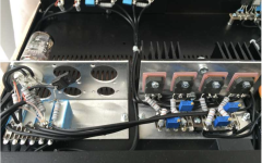
Regarding the bias of 100 to 150mA bias, it is definitely not this, more like less than 50mA, which I know is not the best. If you look at the size of the heatsink, it doesn't support biases of 100mA let alone 150mA from four mosfets. From operating the amp it doesn't get too hot, even with the 12AX7 in there as well. Experience with a Hitachi amp, it had a way bigger heatsink for four mosfets at 75mA and got hotter.
I could recommend a number of changes, such as: 4.7uF cap across the bias pot, 330R for the n-channel gate and 220R for the p-channel. A constant current sink instead of the 100k source resistor. A mosfet with a lower Crss. Biasing the mosfets so than they are in negative temperature co-efficent territory, i.e. greater than 125mA, bigger heatsinks. A constant current source in the biasing resistor chain to stabilise bias etc. Now from an engineering perspective these all make sense but from a sound perspective maybe not. Glenn Croft was a master of using simple circuits and good components to get great sound. Whilst his creations may have not given super low distortion or that last bit of detail or forced you to mortgage your house, they had this ability to relax the listener and make recorded music very enjoyable for a fair price. What more could you ask for!
I don't disagree with Banat about his amp (or guess not quite sure), but as I said Croft used to alter builds accordingly. So his and mine are different in this respect. I spoke to Glenn many, many years ago about this, with regard to his Super Micro A preamp. He admitted to experimenting with components and values, as long as it didn't affect the sound adversely.
Regarding the bias of 100 to 150mA bias, it is definitely not this, more like less than 50mA, which I know is not the best. If you look at the size of the heatsink, it doesn't support biases of 100mA let alone 150mA from four mosfets. From operating the amp it doesn't get too hot, even with the 12AX7 in there as well. Experience with a Hitachi amp, it had a way bigger heatsink for four mosfets at 75mA and got hotter.
I could recommend a number of changes, such as: 4.7uF cap across the bias pot, 330R for the n-channel gate and 220R for the p-channel. A constant current sink instead of the 100k source resistor. A mosfet with a lower Crss. Biasing the mosfets so than they are in negative temperature co-efficent territory, i.e. greater than 125mA, bigger heatsinks. A constant current source in the biasing resistor chain to stabilise bias etc. Now from an engineering perspective these all make sense but from a sound perspective maybe not. Glenn Croft was a master of using simple circuits and good components to get great sound. Whilst his creations may have not given super low distortion or that last bit of detail or forced you to mortgage your house, they had this ability to relax the listener and make recorded music very enjoyable for a fair price. What more could you ask for!
Attachments
Hi Ejam,
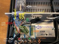
Thank you for the update. Just a question. The picture you show of the internals of the amp is not yours? I guess not as there seems to be 1K resistors on the cathode as per Banat's modified schematic.
Still, the use of diodes or leds in the cathode is often used. So I'm sure it's correct in your case. Although as rayma writes, I would probably have chosen an led or 1N4148 instead of 1N4007. But, perhaps it's dynamic resistance is close to 1K at such low currents.
MKC
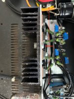
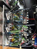
Yes the picture is not mine, just grabbed it off the web, far easier than going down to the garage and opening the amp yada, yada, yada. You guys are restless with this diode thing. Again I say it was Glenn's choice not mine, if you want to use a resistor or LED or fixed bias or whatever, knock yourself out. To satisfy the pundits, have included photos of my amp for you, taken just now. Before I get "but that's not a Series 7", yes it is an "Integrated" which is the Series 7 power amp mated to the Croft 25 preamp phono stage, hence the three 12AX7, as confirmed by Glenn himself.
Yes the picture is not mine, just grabbed it off the web, far easier than going down to the garage and opening the amp yada, yada, yada. You guys are restless with this diode thing. Again I say it was Glenn's choice not mine, if you want to use a resistor or LED or fixed bias or whatever, knock yourself out. To satisfy the pundits, have included photos of my amp for you, taken just now. Before I get "but that's not a Series 7", yes it is an "Integrated" which is the Series 7 power amp mated to the Croft 25 preamp phono stage, hence the three 12AX7, as confirmed by Glenn himself.
Attachments
Hi Ejam,
Sorry, if I (we) comes across as critical. It's not my intention and I'm sure everybody else agrees. I really appreciate the information you have provided. Thank you for that. All the various details and variations are just interesting.
For me this is just a matter of getting these amplifiers documented as Croft is no more, as I understand it. So people searching for info might find this thread and get some info for repair and the odd clone.
Now, as you might have noticed some of us is often referred to as the "greedy boys" 🙂 . Any chance for the schematic for the phono-stage?
One of the Croft-7 power amp variant for sure don`t use any diode for each half of the Ecc83 katode autobias but just 1K resistors non-bypassed , also I have seen some DIY variants with LED diode instead of cathode resistors ,Hi Ejam,
Thank you for the update. Just a question. The picture you show of the internals of the amp is not yours? I guess not as there seems to be 1K resistors on the cathode as per Banat's modified schematic.
Still, the use of diodes or leds in the cathode is often used. So I'm sure it's correct in your case. Although as rayma writes, I would probably have chosen an led or 1N4148 instead of 1N4007. But, perhaps it's dynamic resistance is close to 1K at such low currents.
any way IMHO this simple hybrid amp concept can be modified and improved in many different ways , personally I like the simple two stage variant with lateral Mosfets OPS biased around 300mA, which enlarge amplifier A-class area of operation , where OPS is directly driven from triode strapped EL84 anode via two coupling caps .
Attachments

Banat
Regarding the regulator, mine is the same as your photo. I like your idea about using an EL84 to drive the output. I also like a SRPP driver using a 6N6P. All these ideas however are way beyond the Croft chassis to accomodate, especially the 300mA output bias with its heatsink requirements.
Having the 12AX7 directly coupled to the mosfet will have issues over time as the 12AX7 ages. The voltage at the anode sets the bias point for the mosfet and as the 12AX7 ages, this will affect the mosfet's operating condition.
MKC
No offence taken. I'll see if I can dig up the phono schematic, somewhere in my notebooks....
Having the 12AX7 directly coupled to the mosfet will have issues over time as the 12AX7 ages. The voltage at the anode sets the bias point for the mosfet and as the 12AX7 ages, this will affect the mosfet's operating condition.- Ejam I Apsolutelly agree with you ! , for long term DC stability wise OPS have to be galvanicaly separated from input VAS & driver stage .

- Home
- Amplifiers
- Tubes / Valves
- Croft Series 7