Hi Folks,
I just discovered that I may have sent out the incorrect version of the SFPP to those of you who recently placed orders for one. That’s what happens when two boards don’t have version designators on the silkscreen (my fault completely).
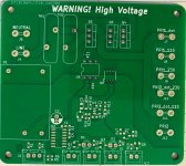
If you by chance got the incorrect board (the new one) it will look like this:

The two tiny 3mm x 3mm 0.65mm pitch SMT chips are replaced by a much larger single easy to solder SOIC chip with large pads.
Please contact me if this happened to you and I can send you the correct board, or send you the correct BOM and you can continue on. There are a few minor changes to the ancillary components but most of the rest of the BOM will be the same.
Again, sorry for the mixup.
I just discovered that I may have sent out the incorrect version of the SFPP to those of you who recently placed orders for one. That’s what happens when two boards don’t have version designators on the silkscreen (my fault completely).
If you by chance got the incorrect board (the new one) it will look like this:
The two tiny 3mm x 3mm 0.65mm pitch SMT chips are replaced by a much larger single easy to solder SOIC chip with large pads.
Please contact me if this happened to you and I can send you the correct board, or send you the correct BOM and you can continue on. There are a few minor changes to the ancillary components but most of the rest of the BOM will be the same.
Again, sorry for the mixup.
Hi Folks,
A member has graciously agreed to be the beta tester for the new easier to solder circuit. I am now taking preorders on the new version PCB, the circuit change should be straightforward so Indint anticipate any problems.
https://xrkaudio.etsy.com/listing/1460330112
The only change to the circuit is to remove the older 0.65mm pitch U2 and U3 parts and replace with a single Nexperia 74LVC07AD,118 now called U2. These are SOIC-14 with exposed legs so very easy to solder.
Here is the new SFPP V2.3EZ schematic:

And here is the BOM:

A member has graciously agreed to be the beta tester for the new easier to solder circuit. I am now taking preorders on the new version PCB, the circuit change should be straightforward so Indint anticipate any problems.
https://xrkaudio.etsy.com/listing/1460330112
The only change to the circuit is to remove the older 0.65mm pitch U2 and U3 parts and replace with a single Nexperia 74LVC07AD,118 now called U2. These are SOIC-14 with exposed legs so very easy to solder.
Here is the new SFPP V2.3EZ schematic:
And here is the BOM:

Hey all, I'm the beta guy, and I've created a Mouser cart to share if anyone wants to use it. The only difference from the BOM above are the JST header connecters - I went with the right angle ones because the vertical ones were backordered. I also added the wire end crimp terminals and housings for those.
https://www.mouser.com/ProjectManager/ProjectDetail.aspx?AccessID=6c9a4e6ba4
Please make a copy of the cart for yourself and don't edit mine! 🙂
https://www.mouser.com/ProjectManager/ProjectDetail.aspx?AccessID=6c9a4e6ba4
Please make a copy of the cart for yourself and don't edit mine! 🙂
Thanks, Gthibodeaux! You can get imitation JST’s in kits on Aliexpress or Amazon. They work well enough. Appreciate you being the tester.
@xrk971 Can you tell me which is pin 1 on the new pcb for the dual flip flop (U2)?Hi Folks,
A member has graciously agreed to be the beta tester for the new easier to solder circuit. I am now taking preorders on the new version PCB, the circuit change should be straightforward so Indint anticipate any problems.
https://xrkaudio.etsy.com/listing/1460330112
The only change to the circuit is to remove the older 0.65mm pitch U2 and U3 parts and replace with a single Nexperia 74LVC07AD,118 now called U2. These are SOIC-14 with exposed legs so very easy to solder.
Here is the new SFPP V2.3EZ schematic:
View attachment 1446720
And here is the BOM:
View attachment 1446722
Last edited:
Well, it looks like I ordered the wrong format of this optocoupler and the pins are too wide, and if I bend the pins it'll stand off of the board... Do I need to reorder it or will this work all the same, to and just look a bit wonky?


That is the correct format - looks like a 6-pin DIP through hole package. The pins just need to be bent to fit the width of the two rows. What part did the BOM spec? You might want to solder the SMT Dual FlipFlop before installing C2 to make room for the soldering iron.
If you look at the silk screen label, there is a bar where U2 is located. The bar extends out parallel to Pin 1 solder pad. Whereas the other pins don't have a bar that extends to to pin solder pad. So looking at the board with text oriented correctly at top, Pin 1 is top left corner.@xrk971 Can you tell me which is pin 1 on the new pcb for the dual flip flop (U2)?
I meant to say pin dimensions/layout. The BOM called for MOC3022M, and I inadvertently got MOC3022TVM. Basically the same, just different physical specs as far as I can tell...That is the correct format - looks like a 6-pin DIP through hole package. The pins just need to be bent to fit the width of the two rows. What part did the BOM spec? You might want to solder the SMT Dual FlipFlop before installing C2 to make room for the soldering iron.
I'm using my hot air station - think I should still pull that cap ?
If you use a hot air station be careful not to overheat the electrolytic cap. They are kind of temp sensitive.I meant to say pin dimensions/layout. The BOM called for MOC3022M, and I inadvertently got MOC3022TVM. Basically the same, just different physical specs as far as I can tell...
I'm using my hot air station - think I should still pull that cap ?
I would recommend not using hot air for your situation. That adds too much heat to the surrounding components and C2 will block the air. I like to solder all the surface mount parts before any through hole parts are installed.
The pads for the SOIC part are slightly elongated making hand soldering very easy.
Melt a small blob of solder on one corner pad, apply flux to this blob and all the pads, position the part (it won’t sit flat because of the solder blob), gently apply pressure on top of the part with tweezers as you re-flow the solder blob with your iron. Now the part sits flat and is tacked in place. Hit the opposite corner leg with iron and solder. Now the part is secure and you finish off the rest of the legs. Take your time so you don’t overheat the part.
Well, it's put together... My 3rd time using a hot air station (for most of the components) went pretty well. I did make a few dumb errors along the way, but hopefully it'll work as expected once I get a chance to set it up in my ongoing AN39 project.
I realize the soldering work isn't perfect by any means, but am hoping it's good enough, and will stand the test of time.
If anyone sees anything that's concerning please let me know so I can address it. Also, I'd appreciate any suggestions for a test methodology that might prevent any potential damage to this or other connected components!
Thanks,
Greg
Looks pretty good. Make sure you have D4 aligned correctly or it won’t work if backwards. If you plan to use external LEDs on the indicators where the JST jacks are, you need to remove the onboard LEDs D1 and D2, as you can’t drive both simultaneously.
For testing, connect at 2kohm 10w power resistor to the output as a dummy load. Or connect primaries from a power trafo.
You need the momentary pushbutton switch to activate it.
Like this:

Good luck!
For testing, connect at 2kohm 10w power resistor to the output as a dummy load. Or connect primaries from a power trafo.
You need the momentary pushbutton switch to activate it.
Like this:
Good luck!
One other note, when you verify the board works as it should, cover the mosfets and D5 with shrink tubing for safety.
Good luck!
Good luck!
X, I watched you YouTube Video. I have a a few questions,
I watched the video and learned about the thermal Switch, What thermal device and where is it placed?Vunce is correct. These are two different boards (products). Unfortunately, they have similar names and the rev numbers are similar at circa 2.2/2.3.
SFP (soft as a feather pillow) has no remote on/off capability. Just soft start. Latest is 2.3
SFPP (soft as a feather pillow plus) has remote on/off capability plus remote shutdown due to safety trigger. Latest is 2.2.
I am working on an update to SFPP that doesn’t use those pesky SMT flip flop and NANDs with tiny hidden solder pads.
Get a normally open switch - coffeemaker thermostat. I typically choose 85C trip point. Mount it on the heatsink, and if it ever closes, the SFPP shuts down and requires a power cycle to reset. If you have more than one, wire them in parallel. Any one will set it off as a logical OR function. You can test the functionality by shorting or closing the contacts of the JST connector pins.
Like this:

Like this:
- Home
- Group Buys
- Soft as a Feather Pillow (SFP) SSR Soft Start Circuit GB