Comparing v.2.2 against v2.3, the latest iteration got rid of the indicator LED's which could be routed to the front. I enjoyed this feature of v2.2. Would there be any issues moving forward with v.2.2 or does it have stability issues ?
As I see it, the option still exists. You can load the on board status LEDs or off board via the associated headers. Just not both.

Just such that there is no confusion
v.2.2


v2.3


I can see use cases for both and one doesn't always need additional status information such as can be see on v2.2 nor a momentary switch... but I like that stuff 😉 so in light of that, I will stick to v2.2.
Gonna be interesting what is cooking in your brain for v2.4 .. who knows what untapped potential you see
v.2.2
v2.3
I can see use cases for both and one doesn't always need additional status information such as can be see on v2.2 nor a momentary switch... but I like that stuff 😉 so in light of that, I will stick to v2.2.
Gonna be interesting what is cooking in your brain for v2.4 .. who knows what untapped potential you see
The version history is not applicable here because the through-hole SFP board is a different design compared to the smt SFP+ board.
Apples to oranges 😁
Apples to oranges 😁
Vunce is correct. These are two different boards (products). Unfortunately, they have similar names and the rev numbers are similar at circa 2.2/2.3.
SFP (soft as a feather pillow) has no remote on/off capability. Just soft start. Latest is 2.3
SFPP (soft as a feather pillow plus) has remote on/off capability plus remote shutdown due to safety trigger. Latest is 2.2.
I am working on an update to SFPP that doesn’t use those pesky SMT flip flop and NANDs with tiny hidden solder pads.
Aah, I didn't think about the TH vs SMD... kewl. Thanks for pointing it out, besides the other attributes.
So the newer SFPP will use easier to solder parts ?
So the newer SFPP will use easier to solder parts ?
Can someone help me with the tlp3906 u2 photodiode optocoupler. Is there a direction this needs to be soldered on the board? Ive Never used one of these before. Thanks! Btw I have sfp v2.3.
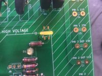
Big Circle designates pin 1 according to this pic diagram:

Pin 1 should be connected to the 5V line right? See schematic post 283 above.
There should also be a mark on the PCB designating pin 1.
Best,
Anand.
Pin 1 should be connected to the 5V line right? See schematic post 283 above.
There should also be a mark on the PCB designating pin 1.
Best,
Anand.
Correct! Also notice how the trace next to it would connect to pin 3 of tlp3906e since it has R5 and D1 connected to it too.

Best,
Anand.
Best,
Anand.
Anand,
If you don’t mind. Can you help me understand what this part is doing?I don’t understand.
Thnx,
If you don’t mind. Can you help me understand what this part is doing?I don’t understand.
Thnx,
I’m not even close to an expert but I’ll try.
An optocoupler (U2 in your schematic) is an interesting device and highly useful in electronics. I first learned about optocouplers when analyzing the Pass M2 output stage and reading his well written patent.
This application in this softstart circuit however is different.
Two parts are used in an optocoupler: 1) an LED that emits infrared light and 2) a photosensitive device that detects light from the LED. Both parts are contained within the black box with pins for connectivity. The input circuit takes the incoming signal, whether the signal is AC or DC, and uses the signal to turn on the LED. The photosensor is the output circuit that detects the light and depending on the type of output circuit, the output will be AC or DC. Current is first applied to the optocoupler, making the LED emit an infrared light proportional to the current going through the device. When the light hits the photosensor a current is conducted, and it is switched on. When the current flowing through the LED is interrupted, the IR beam is cut-off, causing the photosensor to stop conducting.
There are many applications for optocouplers but I don’t want to bore you. In this application, it appears to be a mosfet gate driver (Q1 and Q2 in the schematic) , and essentially we are using small digital voltages to control large AC signals (i.e. as a mains soft start to control the 120V mains voltage).
I’m sure the designer @jhofland can expand even more and teach us.
Best,
Anand.
Last edited:
Hi all,
I would like to build a high quality mains filter with 3000W isolation transformer + EMI. If the mosfets will be cooled, can I use this softstart on a 3000W toroid?
Thanks 🙂
I would like to build a high quality mains filter with 3000W isolation transformer + EMI. If the mosfets will be cooled, can I use this softstart on a 3000W toroid?
Thanks 🙂
3000VA and 220v means 13.6A. I think the MOSFET can handle that current.
Rated 44A and 0.067ohm RDson.
https://www.onsemi.com/pdf/datasheet/fcp067n65s3-d.pdf
Rated 44A and 0.067ohm RDson.
https://www.onsemi.com/pdf/datasheet/fcp067n65s3-d.pdf
Anand has it right. Optocoupler here is specifically designed as a MOSFET gate driver. Why is it used? To galvanically isolate the high voltages in the main current flow from the control logic. From safety standpoint we want to keep mains voltages from having possibility of touching low voltage circuits for shock hazard. It also reduces hum pickup on the lower voltage circuit.
- Home
- Group Buys
- Soft as a Feather Pillow (SFP) SSR Soft Start Circuit GB