And one thing just as certain is that anyone can spread lots of unsubstantiated claims on this forum.Let's not talk about this pseudo-document, please.
But one thing is as certain as the Amen in the church, every MM system is perfectly suitable for a very high-impedance termination.
kindly,
HBt.
Hans

Yes, I mean the crosstalk curves. What is the non-nonsensical explanation of that behaviour?If you mean crosstalk, then I think what you have been told is absolute nonsense.
Even no documented @ Hans Polak budget cartridge work well, as in attachI think most of the cartridges in the Hans Polak document should work well with 150 kohm, by the way.
Attachments
Load capacitance 400 pF to 500 pF according to the user manual at https://www.shure.com/en-US/Search?...[0][values][0]=Documents&filters[0][type]=any
200 to 300 pF for V15 typeIV - https://service.shure.com/s/article/v15-type-iv-specifications?language=en_US®ion=en-USLoad capacitance 400 pF to 500 pF
So, do you mean to obtain the cartridge's properties from apparent TVV47's parameters?The circuit of the TVV47 is an open secret - and therefore the complex load of the system is also known (the ac input resistance of the preamplifier).
Did they (DUAL) made clear what was the cable capacitance?
Goededag, dear Hans.Hans
I'd like to create a model for my Ortofon OMP cartridge as per your article.
I have a network analyser (the NanoVNA-H) which is capable to measure from as low as 900Hz (as claims its' firmware author). Could you please help me to convert a plot into model's parameters?
Dankjewel!
PS
As NanoVNA-H is a toy, actually, it does measure accurately only the networks having impedances close to 50 Ohm. At several kiloOhms it not accurate and may err at ±10% of the true value. I suspect - this may be the showstopper for me...
Hello!
I can't remember a time in my childhood and youth when people talked about optimal termination capacitor.. However, I assume that the (total) capacity in question must have been in the order of 200pf to 400pf, as the DIN connection cables of the time were often quite long, plus plugs and sockets ...
HBt.
I can't remember a time in my childhood and youth when people talked about optimal termination capacitor.. However, I assume that the (total) capacity in question must have been in the order of 200pf to 400pf, as the DIN connection cables of the time were often quite long, plus plugs and sockets ...
I do not know why DUAL did not specify a C_term, one can only make assumptions. They probably didn't want to confuse the customer unnecessarily. But one thing is clear: if SHURE specifies a capacitance of >220pF, then the frequency-dependent losses in relation to Re(Z) and Im(Z) are high. In other words, the pure inductance value of the MM system drops considerably, while the resistive component rises slowly. There can be no other explanation for such a large terminating capacitance. L_cart (of f) falls.Load capacitance 400 pF to 500 pF according to the user manual (...)
HBt.
That would imply that the smaller the initial MM’s inductance the larger the needed inductance will have to be.
Many Carts needing much smaller cap values are telling a different story.
Instead of this being the “only” explanation, the mechanical part of this Sure V15 Cart may have an early roll off that has to be compensated by a higher Q of the electrical part by using a relatively high cap value.
Hans
Many Carts needing much smaller cap values are telling a different story.
Instead of this being the “only” explanation, the mechanical part of this Sure V15 Cart may have an early roll off that has to be compensated by a higher Q of the electrical part by using a relatively high cap value.
Hans
I’ve sent you a PMGoededag, dear Hans.
I'd like to create a model for my Ortofon OMP cartridge as per your article.
I have a network analyser (the NanoVNA-H) which is capable to measure from as low as 900Hz (as claims its' firmware author). Could you please help me to convert a plot into model's parameters?
Dankjewel!
PS
As NanoVNA-H is a toy, actually, it does measure accurately only the networks having impedances close to 50 Ohm. At several kiloOhms it not accurate and may err at ±10% of the true value. I suspect - this may be the showstopper for me...
Hans
That would imply that the smaller the initial MM’s inductance the larger the needed inductance will have to be.
Many Carts needing much smaller cap values are telling a different story.
Instead of this being the “only” explanation, the mechanical part of this Sure V15 Cart may have an early roll off that has to be compensated by a higher Q of the electrical part by using a relatively high cap value.
Hans
See post #17. The blue curve doesn't look high-Q to me. It looks more like a gradual roll-off to correct for a highish-Q mechanical resonance. The inductance as a function of frequency can be calculated from the impedance magnitude and phase data, if anyone should want to do so.
If you replace the second inductance word with the word terminating-capacitor, it becomes a shoe.That would imply that the smaller the initial MM’s inductance the larger the needed inductance will have to be.
1/omega = sqrt(L*C)
The agreement was once: "terminate with 47kOhm."Many Carts needing much smaller cap values are telling a different story.
47000 [V/A] = sqrt( L/C)
Let's stay on the purely electrical side for a moment and ignore the mechanical part.Instead of this being the “only” explanation, the mechanical part of this Sure V15 Cart may have an early roll off that has to be compensated by a higher Q of the electrical part by using a relatively high cap value.
15000 [1/sec] = 1/ ( 2*PI * sqrt( L*C ) )
These are the first parameters: we know that L_cartridge decreases in value with increasing frequency f (or omega), which implies a different capacitance as termination from the starting point, if we take Z(fh) and fh itself as defined constants.
And only now do we turn to the mechanical influence (of the masses, the oscillator and the trafo, ...) on our desired frequency response.
#
The said Shure system (a sanctuary) should be sufficiently known and described after more than 50 years of pure existence. We no longer need to guess any riddles here.
HBt.
Psst.
And we go around in circles!
Correction, it should of course have been :That would imply that the smaller the initial MM’s inductance the larger the needed inductance will have to be.
Many Carts needing much smaller cap values are telling a different story.
Instead of this being the “only” explanation, the mechanical part of this Sure V15 Cart may have an early roll off that has to be compensated by a higher Q of the electrical part by using a relatively high cap value.
Hans
That would imply that the smaller the initial MM’s inductance the larger the needed capacitance will have to be.
Hans
I just reacted to the fact that the "only" explanation could be .....See post #17. The blue curve doesn't look high-Q to me. It looks more like a gradual roll-off to correct for a highish-Q mechanical resonance. The inductance as a function of frequency can be calculated from the impedance magnitude and phase data, if anyone should want to do so.
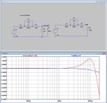
But using the measured |Z| values that hbtaudio presented, I made a coarse model having within a few percent the same impedance values, see first attachment.
Coarse because the presented measured data is not very accurate but rounded to 1000Ohm steps and because it only goes up to 20kHz, but anyhow good enough for a start to get more insight.
In a LTSpice model with 47K//400pF as well as a second version with 150K termination load the Generators response for both versions could be determined, see second attachment. The 11K resistance //120mH is caused by and represents the eddy current losses.
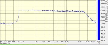
Now looking at the V15 III frequency response in #35, the overall FR can be found, from +1dB@2Khz to -1dB @10Khz and back to +1dB@20Khz.
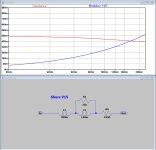
Assuming the measured impedance values from hbtaudio to be relatively correct, the mechanical FR can now be determined by subtracting the generators response from the overall response.
See third attachment.
The upper part is for a 47K+400pF termination.
The mechanical FR must have a high Q to compensate for the generators roll off, both together resulting in the FR as in #35.
Now using a 150K termination it will have to deal with the same mechanical FR, that's why overall response becomes rather dreadful, varying from -3.5dB to almost +6dB.
As a conclusion from these simulations based on the above input data, this Shure cartridge does not seem a good candidate for a 150K termination.
Hans
Attachments

Dear Hans P.I just reacted to the fact that the "only" explanation could be .....
But using the measured |Z| values that hbtaudio presented, I made a coarse model having within a few percent the same impedance values, see first attachment.
Coarse because the presented measured data is not very accurate but rounded to 1000Ohm steps and because it only goes up to 20kHz, but anyhow good enough for a start to get more insight. (...)
These are the datas of the famous article by Marcel vdG.

HBt.
Coarse because the presented measured data is not very accurate but rounded to 1000Ohm steps and because it only goes up to 20kHz, but anyhow good enough for a start to get more insight.
Is this thread actually going to be the continuation of this
Faden ?
@Hans Polak
What frequency resolution do you want - and in which decades?
1 - 10Hz
df=0.1Hz
10Hz - 100Hz
df=1Hz
100Hz - 1kHz
df=10Hz
1kHz - 10kHz
df=100Hz
10kHz - 100kHz
df=1kHz
100kHz - 1MHz
df=10kHz
???
Please let us know the key data of your preferred vector voltmeter or whatever you use.
HBt.
Now looking at the V15 III frequency response in #35, the overall FR can be found, from +1dB@2Khz to -1dB @10Khz and back to +1dB@20Khz.
We do not know the C_term of the DUAL measurement (posting #35), but never 400pF in total, never!
But I understand your objection, dear Hans P.
HBt.
👍
To evaluate the impending disappointment (regarding my expectations of LR75µs benefits) I created a fictitious cartridge model based on this Hans Polak's document. Factory specs for Ortofon OMP are 450 mH+750 Ohm.

With my realistic cable capacitance (and switching the needle+vinyl resonance off) the LCR behaviour is not so frightening:

But the needle+vinyl resonance at ~38kHz changes the nice-looking picture drastically:

It may be somewhat tamed by Cinp == 1n5, but that is far from what I dreamed about:

With my realistic cable capacitance (and switching the needle+vinyl resonance off) the LCR behaviour is not so frightening:
But the needle+vinyl resonance at ~38kHz changes the nice-looking picture drastically:
It may be somewhat tamed by Cinp == 1n5, but that is far from what I dreamed about:
Last edited:
As a conclusion from these simulations based on the above input data, this Shure cartridge does not seem a good candidate for a 150K termination.
Nice to know that you and Nick (post #31) both agree with my conclusion from post #20.
- Home
- Source & Line
- Analogue Source
- I'm interested in RIAA preamps design