https://www.allaboutcircuits.com/technical-articles/understanding-inductors-with-gapped-cores/Did anyone mention that a flyback transformer/inductor needs to have a gapped core? Gapped cores are much harder to saturate and store more energy than un-gapped cores.
I wasn't aware of the existence of them!
Hello,
This kind of transformer works with the UC3845A.
It can output 500V+ and is much safer than the yellow transformers from Aliexpress.
Wurth 750845240
https://www.we-online.com/components/products/datasheet/750845240.pdf
Regards,
Stef.
This kind of transformer works with the UC3845A.
It can output 500V+ and is much safer than the yellow transformers from Aliexpress.
Wurth 750845240
https://www.we-online.com/components/products/datasheet/750845240.pdf
Regards,
Stef.
This is 30x30x20mm. Sure you got galvanic isolation but it's bigger than SRP1265A 13x13x6mm.
Thanks for suggestion, for other builds, like a real 12V > 500V premp (+PA) head amplifier.

Hello Gebrey,
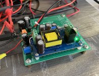
I've uploaded the HV power supply project I'm working on. I should have the first prototype ready in about two weeks.
https://github.com/stefaweb/audio-psu/tree/main/HV-MODULE-UC3845-1.0
In addition to the HV module, I've also created a board to mount the module, add a 30 KHz output filter and manage the negative voltage for the BIAS.
https://github.com/stefaweb/audio-psu/tree/main/TUBE-HV-PSU-45W-1.0
So far, I've only tested it with HV Chinese modules at 350V/60mA and -60V.
Regards,
Stef.
Attachments
Wow! What a job!I've uploaded the HV power supply project I'm working on. I should have the first prototype ready in about two weeks.
Since Im a beginner in this field I have some questions.
I barely understood the suggested UC3845 scheme.
This one is so improved!
Let check if I got every implementations.
Red area: voltage regulator. But... why we need it? UC38xx allows for 36V max rating. We could use 24V directly. My project would involve max 18V.
Green area: why 2 primary in parallel?
Yellow area: what is -HVo? Is it a predisposition to have 0 as virtual ground?
Why are these caps doubled with 2x 1M resistors? Why not just 1 cap and 1 resistor?
Cyan area: feedback circuit to comp pin? And is the switch MMBT3904 in purple area used to power off UC switching via comp pin instead of turning off for absence of Vcc?
Thanks
One of the best tools you can have when testing an SMPS is an AM radio.
Before getting to deep into the swamp, I would suggest reading Jim Williams white papers and watching this video he did for Linear Tech before he passed away.
https://www.analog.com/en/resources/app-notes/an-118fb.html
Before getting to deep into the swamp, I would suggest reading Jim Williams white papers and watching this video he did for Linear Tech before he passed away.
https://www.analog.com/en/resources/app-notes/an-118fb.html
Green: look at the Wurth transformer specs. The transformer is upside down.
Yellow: the module can output more than 500V. It's less expensive to use low voltage caps. Caps over 500V are also hard to find. The 1M resistors are used to balance the caps.
Cyan: The LM358 is only used if you want to create a negative voltage with the module. The circuit with the MMBT3904 allows you to create an on/off with a low level signal (external time delay by relay on power-up).
The "-BIAS" is used to output -150V/-200V to control a tube's BIAS (no load) with the second PCB which contains a divider bridge to go between -30V and -80V. It is experimental. I have not yet tested this configuration with my module. It works with the Chinese blue module that I tested as a prototype or I even put 2 diodes on the same transformer winding. The problem with the blue module that I tested is that the transformer is too small. We can only output 15W. The yellow module does not work and is even dangerous (among other things the overvoltage circuit is defective and it outputs 650V at times at startup).
The module's frequency is 47KHz, far outside the audio range. I added a 30KHz filter at the output on the second PCB to filter out anything coming from the AC-DC power module (as the IRM-45-24).
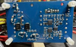
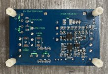
Finally, the schematic is one thing, but the most important thing is how the PCB is made (Look at the ground planes on the PCB around R5). Chinese modules are particularly poorly made, even though their schematics themselves are functional.
Stef.
Yellow: the module can output more than 500V. It's less expensive to use low voltage caps. Caps over 500V are also hard to find. The 1M resistors are used to balance the caps.
Cyan: The LM358 is only used if you want to create a negative voltage with the module. The circuit with the MMBT3904 allows you to create an on/off with a low level signal (external time delay by relay on power-up).
The "-BIAS" is used to output -150V/-200V to control a tube's BIAS (no load) with the second PCB which contains a divider bridge to go between -30V and -80V. It is experimental. I have not yet tested this configuration with my module. It works with the Chinese blue module that I tested as a prototype or I even put 2 diodes on the same transformer winding. The problem with the blue module that I tested is that the transformer is too small. We can only output 15W. The yellow module does not work and is even dangerous (among other things the overvoltage circuit is defective and it outputs 650V at times at startup).
The module's frequency is 47KHz, far outside the audio range. I added a 30KHz filter at the output on the second PCB to filter out anything coming from the AC-DC power module (as the IRM-45-24).
Finally, the schematic is one thing, but the most important thing is how the PCB is made (Look at the ground planes on the PCB around R5). Chinese modules are particularly poorly made, even though their schematics themselves are functional.
Stef.
Attachments
Green: look at the Wurth transformer specs. The transformer is upside down.
I still don't get it. That symbology means one sec is wounded around the other sec? What does that imply? Stronger inductor I guess. We lose half of the potential of the trafo if we skip one of these wounds.
Got it. Also, 1M resistor let caps discharge when power off, right?Yellow: the module can output more than 500V. It's less expensive to use low voltage caps. Caps over 500V are also hard to find. The 1M resistors are used to balance the ccaps.
Mmmh.Cyan: The LM358 is only used if you want to create a negative voltage with the module. The circuit with the MMBT3904 allows you to create an on/off with a low level signal (external time delay by relay on power-up).
Without LM358, is the trimmer RV1 that change sensed voltage (feedback) to adjust Vo.
With the LM358, we invert the voltage sensed to let UC3845 senses and produce negative voltage? I'm not sure.
Also for the presence of these diodes at Vo.
If I want a negative voltage, why simply swap + and 0?
Example.
- + = +500V 0 = GND
- + = GND 0 = -500V
So, D1 create an half wave rectifier.The "-BIAS" is used to output -150V/-200V to control a tube's BIAS (no load) with the second PCB which contains a divider bridge to go between -30V and -80V.
D2 does the same but for the negative part of the wave (negative voltage) and I question if C12 and C13 polarity is right.
A SUGGESTION:
The 15V aux (Wurth pin 5 & 6) could be used to feed Tube heaters like with a LM317 @12.6V if we don't want to take it from UC3845 source.
Hello,
I added an LTSpice simulation of the UC3845 HV module to the Github repository.
https://github.com/stefaweb/audio-psu/tree/main/HV-MODULE-UC3845-1.0
I'm still waiting for my first prototypes.
Regards,
Stef.
I added an LTSpice simulation of the UC3845 HV module to the Github repository.
https://github.com/stefaweb/audio-psu/tree/main/HV-MODULE-UC3845-1.0
I'm still waiting for my first prototypes.
Regards,
Stef.
Hope they come soon!I'm still waiting for my first prototypes.
Can you reply to my previous message to confirm or not my questions? Thanks so much, I'm learning
Hi Gebrey,
Sorry, I'm in vacation. I don't have time to answer all your question.
The schematic you posted was still under development. Since then, it's evolved quite a bit. You can check the GitHub repository from time to time. It's best to avoid posting provisional schematics online here. This can be confusing.
I'll resume testing the prototype when I get back in early May.
Regards,
Stef.
- Home
- Amplifiers
- Power Supplies
- 12V 555 based High Voltage power supply