which makes even more extra noise penalty
I think that depends entirely on how you realize it.
R*(f) in the table2 (by Richard Visee?) @ your "cooling article" still remain a stunning revelation. Maybe Richard has other interesting research?
I don't know. I haven't had much contact with him since he and Gert van der Horn founded SystematIC decades ago.

No, we are not talking about mechanical resonance (it is unchanged both with 5k or 150k load), but about the need to compensate for the frequency response roll-offs caused by the increase in the cartridge impedance due to both its inductance and the even more significant increase in loss resistance (effective series resistance, "iron loss") with frequency @ 5k Rin, - with 150k input we don't have such a significant and most importantly undefined roll-off, then there is no need to raise the standard RIAA.If the 12 dB drop-off that you get with the recommended load is meant to compensate for some mechanical resonance,
My implicit assumption is that the people at Shure knew what they were doing and that they ensured by some means or other that the overall response you get with their recommended load of 47 kohm in parallel with 450 pF is reasonably flat over the audio frequency range.
The cartridge can be represented with a Thevenin equivalent consisting of a voltage source in series with the impedance that Richard Visee measured. (I'm making a second assumption here: Richard measured with the stylus up in the air, not on a record. In fact, the whole cartridge may have been upside down. I assume that doesn't make much of a difference.)
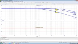
Using this Thevenin equivalent, the transfer from the Thevenin voltage to the terminal voltage with the recommended load drops almost 12 dB from 1 kHz to 20 kHz. Under the assumptions I just made, the transfer from the Thevenin voltage to the terminal voltage then needs to drop approximately 12 dB to get a reasonably flat overall frequency response.
With your 150 kohm, there is no such drop, so a Shure V15-III must sound too bright. The same issue occurs with a 4794.5333... ohm load and a RIAA correction without the 75 us time constant.
The cartridge can be represented with a Thevenin equivalent consisting of a voltage source in series with the impedance that Richard Visee measured. (I'm making a second assumption here: Richard measured with the stylus up in the air, not on a record. In fact, the whole cartridge may have been upside down. I assume that doesn't make much of a difference.)
Using this Thevenin equivalent, the transfer from the Thevenin voltage to the terminal voltage with the recommended load drops almost 12 dB from 1 kHz to 20 kHz. Under the assumptions I just made, the transfer from the Thevenin voltage to the terminal voltage then needs to drop approximately 12 dB to get a reasonably flat overall frequency response.
With your 150 kohm, there is no such drop, so a Shure V15-III must sound too bright. The same issue occurs with a 4794.5333... ohm load and a RIAA correction without the 75 us time constant.
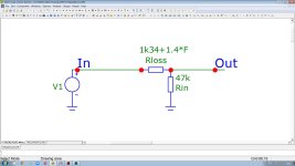
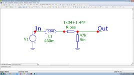
Attached is a zip file with the spreadsheet that produced the graph and the graph itself. The calculation is quite simple, I used the equation for voltage division with admittances (other admittance divided by the sum). The cartridge admittance is Gc + j Bc and the load admittance Gl + j Bl.
For the 4794.5333... ohm case, a term +10*LOG10(1+(0.000075*2*PI()*$An)^2) is added to the decibel value to account for the fact that there will be no pole with 75 us time constant in the RIAA correction network.
For the 4794.5333... ohm case, a term +10*LOG10(1+(0.000075*2*PI()*$An)^2) is added to the decibel value to account for the fact that there will be no pole with 75 us time constant in the RIAA correction network.
Attachments
Last edited:
Yes, they were, but -12 dB @20Khz vs 1 kHz to compensate for the mechanical resonance of the cantilever was in the 70s of the last century with heavy effective tip masses > 0.4 milligrams (including old V15). Today, the effective masses both of MM and MC are already at a level of 4...8 times lighter (0.1 ... 0.05 milligrams, see https://www.audiosciencereview.com/...ivalent-effective-tip-mass-master-list.41783/ ), so there is no mechanical resonance as such, at least up to 30 kHz (the reciprocal value of the square root of the effective mass). I did not see any peaks with AT-VM9x and Orto M2 x most popular MMs today.My implicit assumption is that the people at Shure knew what they were doing [skipped] with their recommended load of 47 kohm in parallel with 450 pF
So you agree with my conclusion from post #20 that without extra correction filters, the Shure V15-III is not suitable for 150 kohm load, nor for a RIAA amplifier that realizes the 75 us time constant by means of a 4794.5333... ohm load?
If you have suitable equipment, could you measure the impedance of one of your low-effective-tip-mass cartridges and plug the result and the cartridge's recommended load in the spreadsheet? You should see only small differences between the traces then. The cartridges you mentioned don't seem to be covered in https://www.diyaudio.com/community/attachments/mm-paper-pdf.1161286/
If you have suitable equipment, could you measure the impedance of one of your low-effective-tip-mass cartridges and plug the result and the cartridge's recommended load in the spreadsheet? You should see only small differences between the traces then. The cartridges you mentioned don't seem to be covered in https://www.diyaudio.com/community/attachments/mm-paper-pdf.1161286/
Last edited:
That document comes from this thread: https://www.diyaudio.com/community/...ts-with-individual-transfer-functions.397815/
Goededag, Marcel!!!
Dankjewel for that document!
As I have the Ortofon OMP40 cartridge here I read the document from that angle. Very educational.
I was lured by the 75µs Damped Loading idea because of a model similar to the shown at Fig.13, where the FR extention is promised. Now I'm not so optimistic. Will see what transpires from 75µs Damped Loading implementation at my preamp.
As a side note: I see the needle+groove resonance at 38kHz with my Stylus 40, and before that - with Stylus 10 - it sat at 24kHz. Both are rather high-Q ones.
Also (while I'm yet at 47k+280pF termination) there is a low-Q LC-resonance from the coil+cable sitting at ~20kHz, which I wanted to get rid of by damped loading. It is difficult to get the cable capacitance much lower in my rig.
A side note #2: the 47k termination I have for now is actually by electronically cooled 560k resistor.
Last edited:
Yes I agree with that Shure V15-III is not suitable for any naked resistive load (150-47-5k) without extra correction (@ 47k also, - needed 450 pF for -12 dB @ 20kHz). IMHO the best way of such a -12 dB extra correction is (if needed for old heavy tip mass) corresponding painless and simple increase of the time constant of 75 µs in the feedback circuit. But may be you also agree with my conclusion that 75µs Damped Loading makes much more (as can be seen in #14) noise ? I am attaching several additional nuances on the frequency response taking into account the frequency dependence of the series resistance of the cartridge losses. According to the data from your table2 R* of V15 @ DC is 1.34k but @20k became 30.1k (I can quickly simulate it in Microcap as 1k34+1.4*F using <fexpr> attribute ), - which even without taking into account the cartridge inductance results in a 16.7 (!) dB frequency response roll-off at 20 kHz, which is much more than the roll-off due to the 1.34 Henry inductance (for naked damped 75 µs/5 kOhm). This rolloff not conditioned by damped input time constant Lcart/Rin but by exclusively resistive "iron loss", and few people even guess about it. But do you agree that it exists?So you agree with my conclusion from post #20 that without extra correction filters, the Shure V15-III is not suitable for 150 kohm load, nor for a RIAA amplifier that realizes the 75 us time constant by means of a 4794.5333... ohm load?
Attachments

Last edited:
When you just use a plain old resistor across the input, you get much more noise. When you realize the input impedance with the shunt feedback of a Hoeffelman and Meys-like configuration, you probably still get a noise increase as you can't increase the gain arbitrarily, but it will not nearly be as much noise as with a plain old resistor across the input.
The figure of post #17 and the spreadsheeh of post #25 take into account the frequency-dependent series resistance. You don't see a > 16.7 dB drop because for the 4794.5333... ohm load, I just calculated the difference between the response and the response of an ideal 75 us first-order low-pass.
I think most of the cartridges in the Hans Polak document should work well with 150 kohm, by the way.
Last edited:
Agree, see the right spectrogram - no any peaks at HF [I think most of the cartridges in the Hans Polak document should work well with 150 kohm, by the way.
Goededag, Marcel! I thanked you for the link to the document.You can better thank @Hans Polak , it's his work.
(just gone there and thanked Hans Polak too)
DUAL obviously achieved a very, very good frequency response in the 1970s with their TVV47 two-transistor equalizer. The circuit of the TVV47 is an open secret - and therefore the complex load of the system is also known (the ac input resistance of the preamplifier).

Let's not talk about this pseudo-document, please.I think most of the cartridges in the Hans Polak document should work well with 150 kohm, by the way.
But one thing is as certain as the Amen in the church, every MM system is perfectly suitable for a very high-impedance termination.
kindly,
HBt.
(Elsewhere) I was given an explanation for the sharp rise of the cross-channel leakage (10kHz to 20kHz) - it is caused by the cantilever's own resonance due to its' insufficient rigidity and excessive mass.
If you mean crosstalk, then I think what you have been told is absolute nonsense.(Elsewhere) I was given an explanation for the sharp rise of the cross-channel leakage (10kHz to 20kHz) - it is caused by the cantilever's own resonance due to its' insufficient rigidity and excessive mass.
Why is there no recommended load capacitance on the list?
- Home
- Source & Line
- Analogue Source
- I'm interested in RIAA preamps design