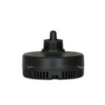
I bought two big horns this type, HL-1018:

46.3*24.4*21.4cm Wide*High*Deep*
and some real drivers Kenford comp50 with Titan diaphragm.
Not tried until now the classic driver for the horn but bought just for fun a Piezo screw on drivers GT-1188.
And did measure only a response down to 4khz like with the small tweeters like KSN1005 what left me puzzled

So did the real Motorola KSN1188 ever really reach down to 800 hz as pretended ? (did not find a measurement online of it).
And is the GT-1188 as a spare part (with internal step up coil) only not working on this big HL1018 horn?
I know that the piezos can never be as good as real coil drivers but is it possible that the frequency response is so far away from covering the claimed response down to under 1khz?
46.3*24.4*21.4cm Wide*High*Deep*
and some real drivers Kenford comp50 with Titan diaphragm.
Not tried until now the classic driver for the horn but bought just for fun a Piezo screw on drivers GT-1188.
And did measure only a response down to 4khz like with the small tweeters like KSN1005 what left me puzzled
So did the real Motorola KSN1188 ever really reach down to 800 hz as pretended ? (did not find a measurement online of it).
And is the GT-1188 as a spare part (with internal step up coil) only not working on this big HL1018 horn?
I know that the piezos can never be as good as real coil drivers but is it possible that the frequency response is so far away from covering the claimed response down to under 1khz?
in this thread they are discussing the HL1018 plastic horn and modifying it because at the beginning (throat) of it there is a step from 1 inch to 40mm which is not ideal for a horn
https://www.diy-hifi-forum.eu/forum/showthread.php?14725-Dicke-Lippe-riskieren-McGee-HL-1018
https://www.diy-hifi-forum.eu/forum/showthread.php?14725-Dicke-Lippe-riskieren-McGee-HL-1018
just looking up the complete forum - Bill Fitzmaurice who knows the piezos well writes:
The CTS piezos don't really work that low; I've used them extensively for years and the best you can hope for is going to be more like 2.5kHz. That, combined with the tendancy for even a ten to beam badly at 2kHz, would make me lean towards an MTM crossed at 2.5kHz.
You could use a pair of 6.5s or 8s to get the required bass extension and cone area, and wiring them parallel will get the sensitivity up to where padding the tweeter won't be required. The 1165a will do nicely. You still will have to put a lowpass coil on the woofer section to prevent IM problems in any case, unless you can...
You could use a pair of 6.5s or 8s to get the required bass extension and cone area, and wiring them parallel will get the sensitivity up to where padding the tweeter won't be required. The 1165a will do nicely. You still will have to put a lowpass coil on the woofer section to prevent IM problems in any case, unless you can...
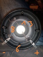
here I measured the gt 1188 on a big HL1018 Horn from Mc Gee. It goes down to 2 khz with a dropping step below 4khz
with a big horn 42cm x 18cm it only does a few db more at 2khz.
Its a joke.


for the horns I bought real drivers as this piezo does no job in it
Its a joke.
for the horns I bought real drivers as this piezo does no job in it
I think the measurement of the original Motorola KSN1188 on the EV 8HD is legit.So did the real Motorola KSN1188 ever really reach down to 800 hz as pretended ? (did not find a measurement online of it).
93dB/1m at 2.83 volts, no step up coil.
That said, it's limiter circuit limited output to ~113dB (28.3volts)
That output would only require ~0.1mm one way movement of the piezo bimorph.
The bimorph will crack if pushed hard.
The 800-30kHz claimed response has no +/- rating, so is not a direct lie even if response is -30dB at each end.And is the GT-1188 as a spare part (with internal step up coil) only not working on this big HL1018 horn?
I know that the piezos can never be as good as real coil drivers but is it possible that the frequency response is so far away from covering the claimed response down to under 1khz?
Looks like the bimorph in the driver you are holding (GT 1188?) is only a fraction of the size of the Motorola KSN1188, I'd expect it simply does not have the excursion capability to make any useful output below 2kHz.
Hence the 4.7uF protection capacitor..
Last edited:
@weltersys
yes its the GT1188
Could be its the smaller piezo disc.
What is a pity is that I cannot reach the paper cone for putting a thin foil of aluminium on it.
The paper cone is glued on so dismantling is impossible.
Get the idea now to bridge the original 4.7uF non polar cap just to see if it makes a difference in response.
If yes - a proper crossover would be better like parallel 33ohms and some capacitor in line for a 6db filtering.
Just wonder if it makes a difference to put this filter before the step up coil or directly before the piezo disc?
I am not sure how the step up coil is wired.
Its not wired like a real step up transformer with two inputs and two outputs and only a magnetic coupling between them.
Looks like one coil in line and one coil parallel to the piezo disc.
On the plus input the piezo disc is directly wired to it.
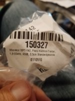
Maybe I will order a MPT-142 screw on piezo driver without coils to see what it does in F response on a big horn like the HL1018.
Its not wired like a real step up transformer with two inputs and two outputs and only a magnetic coupling between them.
Looks like one coil in line and one coil parallel to the piezo disc.
On the plus input the piezo disc is directly wired to it.
Maybe I will order a MPT-142 screw on piezo driver without coils to see what it does in F response on a big horn like the HL1018.
Attachments
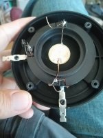

Who understands the wiring of this thing?
If both coils would be separate, o.k. but then somehow magnetically coupled makes no sense to me.
?!
If both coils would be separate, o.k. but then somehow magnetically coupled makes no sense to me.
?!
A transformer has separate primary and secondary coils wound around a magnetic core.Just wonder if it makes a difference to put this filter before the step up coil or directly before the piezo disc?
The input coil resistance might be so low it would look like a short circuit to an amp, requiring the capacitor.
What is the DCR of each coil?

will measure it. A simple resistor could prevent the amp from getting a short, so I could measure the piezo tweeter without this cap.
Ordered MPT-142 to see what a screw on driver without coil will do on that horn.
The coil is wired strangely. I will ask the manufacturer if they have something on this.
Ordered MPT-142 to see what a screw on driver without coil will do on that horn.
The coil is wired strangely. I will ask the manufacturer if they have something on this.
@weltersys
measured it.
The primary to the amp has between plus and minus 6 ohms.
The secondary 13 ohms, measured at the piezo.
However its a standard multimeter which show wrong numbers measuring resistance of inductivities.
But the relation is 1 to 2 giving plus 6db on the tweeter.
Ordered now some noname piezos from aliexpress to see if the Monacor MPT-142 measures or looks different.
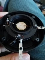
I just dont understand how the coils can work if one pole has a contact directly to the piezo disc.
The coupling between the two coils should be only magnetically?
Measured between plus input and on the solder point of the piezo disc and its connected directly showing zero ohms.
I made a foto with the ohms measured between three points.
measured it.
The primary to the amp has between plus and minus 6 ohms.
The secondary 13 ohms, measured at the piezo.
However its a standard multimeter which show wrong numbers measuring resistance of inductivities.
But the relation is 1 to 2 giving plus 6db on the tweeter.
Ordered now some noname piezos from aliexpress to see if the Monacor MPT-142 measures or looks different.
I just dont understand how the coils can work if one pole has a contact directly to the piezo disc.
The coupling between the two coils should be only magnetically?
Measured between plus input and on the solder point of the piezo disc and its connected directly showing zero ohms.
I made a foto with the ohms measured between three points.
Attachments
Like this:I just dont understand how the coils can work if one pole has a contact directly to the piezo disc.
The primary winding creates a magnetic field when current flows through it.The coupling between the two coils should be only magnetically?
The electromotive force (EMF) from the primary is inductively coupled, even without an iron core.
An air-core secondary winding could be coaxially wound around the primary, or could be interleaved, winding turns of the secondary between the turns of the primary.
Air-core transformers efficiency drops at lower frequencies due to inductive leakage.
Though increasing the voltage at higher frequencies (increasing the "1w/1m" sensitivity), the transformer may behave like a high pass filter even if the capacitor value was increased.
That said, if not protected from low frequencies, the air coils would probably burn up carrying the current needed to drive the piezo below 2kHz.
At any rate, even using a decent ferrite core audio transformer, piezos just don't have enough excursion capability to make much output compared to moving coil transducers at lower frequencies.
They are cheap...
Art
@weltersys
If I want to add a step up transformer to an existing piezo driver - should I wire it the same way as the manufacturer did it?
Does it have any advantage?
If I want to add a step up transformer to an existing piezo driver - should I wire it the same way as the manufacturer did it?
Does it have any advantage?
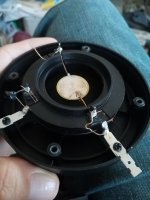
the paper cones have same size (GT1188 and Monacor MPT-142).
The piezo of the MPT disc has three perforations.
The GT 1188 has one in the middle.
Did not ever look at it so exactly to recognize this.
Perforations could help the piezo disc to bend easier?
Does anyone know something on this?
Will measure both piezos.
The piezo of the MPT disc has three perforations.
The GT 1188 has one in the middle.
Did not ever look at it so exactly to recognize this.
Perforations could help the piezo disc to bend easier?
Does anyone know something on this?
Will measure both piezos.
Attachments
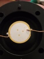
could also be a stain on the piezo disc of the gt1188, so no hole. And the disc looks less tidy, like a b grade piezo
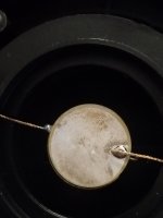
will see if the mpt really does 1,8 khz.
The HL1018 horn goes down to max 400 hz as it is really big.
Would be interesting to know what is the maximum spl of a piezo in a comparison with a classic dynamic tweeter.
The reduced cone travel of the piezo must be severe.
The HL1018 horn goes down to max 400 hz as it is really big.
Would be interesting to know what is the maximum spl of a piezo in a comparison with a classic dynamic tweeter.
The reduced cone travel of the piezo must be severe.
Attachments
Yes.If I want to add a step up transformer to an existing piezo driver - should I wire it the same way as the manufacturer did it?
The transformer steps up voltage, reducing amplifier cost, though amplifier cost is so cheap now that is hardly a consideration.Does it have any advantage?
That said, a good step up transformer uses about as much copper and iron as a moving coil driver, so the cost goes up to near the same price.
At ultrasonic frequencies, piezos may put out more SPL than moving coil drivers.Would be interesting to know what is the maximum spl of a piezo in a comparison with a classic dynamic tweeter.
As far as anything below around 4kHz, the piezo excursion limits output around -12dB compared to an equivalent diameter moving coil high frequency compression driver, a 4/1 (or more) ratio.
The Motorola KSN1188 on the EV8HD horn not only had lousy frequency response (+/-6dB), it was limited to 113dB, while a cheap compression driver like the EV 1823M could hit ~126dB on the same horn.
The KSN1188 was much better than most of the piezos made today.
At high frequencies, (cheap) piezos are power limited, a decent ring radiator could probably put out similar output to ~4 four of the KSN1005 knockoffs.
- Home
- Loudspeakers
- Multi-Way
- GT-1188 Piezo Screw On Driver - KSN1188 alike?