Thank you for posting the BOM , appreciate itNo offense, but this file is a challenge. I just changed it a little. hope you don't mind!
Cheers, Morten

In post #14417 you can see two pictures called "new" and "old" for comparing.
I never had used a boom list before, thanks to m0rten...👍
If i complete my boards i use the printed values on the pcb. The most components i always have in stock. The differece to other board designers may be using both, value and component number...easy to locate something..
Peter
I never had used a boom list before, thanks to m0rten...👍
If i complete my boards i use the printed values on the pcb. The most components i always have in stock. The differece to other board designers may be using both, value and component number...easy to locate something..
Peter
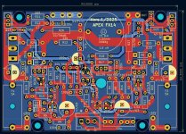
Hi, i have seen that there is a new mistake. As i have updated to the new pcb with other pinouts, KiCad had changed back my mod for the coil. I have corrected that...
the AX14 seems to be not my friend...
Please use this gerberfile to order...
Two mistakes on the pcb are awful....
Peter
the AX14 seems to be not my friend...
Please use this gerberfile to order...
Two mistakes on the pcb are awful....
Peter
Attachments
Hi all. Any assistance would be great. Power amp had a 8amp fuse at back. If not is there soft start as simplest as this that would work? My power had a nasty thump on when I switch it on. Pls assist. ThanxHi all. Would this be suitable for a 600wrms power amplifier? If not, what should I change....Thanx in advance all. Have a blessed 2025
Replace the TRIAC with your desired rated power, choose one with higher current handling capacity than your required current
Power amp draws 8 amps, sivwill get something rated at a higher value. Thank you very much for the infor
hi
i have taransformatorwith 2*22ac please suggset me an amplifier circuit with bjt transistor
tnx
i have taransformatorwith 2*22ac please suggset me an amplifier circuit with bjt transistor
tnx
Hi,
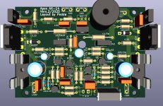
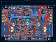
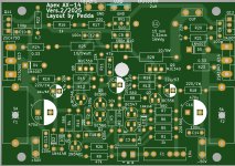
i have desigend a new pcb for the AX14. Perhaps you like it more. The new pcb has more length, less hight, for smaller enclosures with less highness. The boom, and schematic and values are surely the same. Now two versions are available and i hope both pcb will work...
Perhaps i will make a pcb for the mosfet version too...will take time....
Attachments
Still trying to find amp boards that fit on 2U heatsinks. The Dissipante has the brackets covering the heatsinks top and bottom
so even less height available
so even less height available
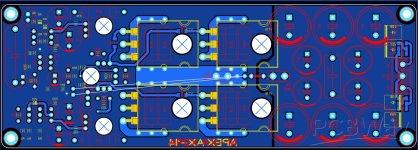
You can order the manufacture of boards, size 62х177мм.
https://www.pcbway.com/project/shareproject/Apex_AX_14_cde80df4.html
https://www.pcbway.com/project/shareproject/Apex_AX_14_cde80df4.html
Attachments
Hi,
awfully i found another mistake on my AX14 pcb's. That is extremely annoying because i dont know the reason. Yesterday afternoon and in this morning i made a new pcb for the Apex FX14. At last i controlled all transistor pinouts. Found out that the pinout of the MJE 350 is not correct. I wonder why and dont know the reason for this mistake. The pinout for the MJE 340 is correct (wtf).
As i registered this i took a look to the AX14 pcb and had to see that there is the same mistake on it. A solution is to solder little wires to the MJE 350 pins and twist the pins 2 and 3 in the right way, possible because the MJE 350 dos not need a heatsink. It is not possible to turn only. Pin 1 is on the same place.
I have the feeling the Apex AX14 don't likes me and plays tricks on me.
So sorry
Peter
Hi,
here with the corrected MJE350.
I have a zip file for the FX14 too. Glad to make it because i found the mistake on the AX14 pcb.
I hope there is no mistake on the pcb. If someone has an idea to make something better tell me...
Greets
Peter
here with the corrected MJE350.
I have a zip file for the FX14 too. Glad to make it because i found the mistake on the AX14 pcb.
I hope there is no mistake on the pcb. If someone has an idea to make something better tell me...
Greets
Peter
Attachments
Hi, i made the ax14, and the sound quality is very good, but one problem I am facing is it hums loudly when no input is connected. If I accidentally switch of the source before the amp, the hum is very irritating. Is there any solution for this?
Never switch off the source before the amplifier! Amplifier should be the last component turned on and first component turned off in powering sequence. This is for any amp not just AX14.
Your hum sounds like a grounding issue, confirm your AX14 is grounded properly.
Your hum sounds like a grounding issue, confirm your AX14 is grounded properly.
This Amp is absolutely salient when the source connected . Some amps I made like p3a don't have any hum with open inputs .
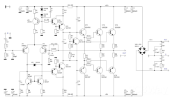
Do some one know which is the last, right schematic ? I had made a pcb, but awful if something is wrong...
My schematic has only one output pair 2SC/2SA. I will compare with the schematic shown in post 14.439 shown with mine. I think there are a few different values.
Peter
My schematic has only one output pair 2SC/2SA. I will compare with the schematic shown in post 14.439 shown with mine. I think there are a few different values.
Peter
- Home
- Amplifiers
- Solid State
- 100W Ultimate Fidelity Amplifier