No, of course I used JFE2140 @6 mA DC with en=0.9 nV/sqrtHz, while the J310 datasheet indicates en=10 nV/sqrtHz ( @10 mA DC , page 2 of OnSemi datasheet-March2006). My bipolar is BC550C biased @ 6 mA (and Rb=0 in MC model), and you use 2SC2547 @ 1.9 mA. I am interested in the reason for using a second bipolar in your differential cascade.Regarding the mixed JFET-bipolar transistor pair, are you sure you used the same transistors as I did (J310 and 2SC2547) and if so, that their noise is properly modelled?
The output impedance of the feedback network was such that I could get a lower noise with a 2SC2547 than with a J310 as the right branch of the differential pair, as described in the article. If that doesn't answer your question, then I don't understand your question. The graphs in the Siliconix J310 datasheet showed far less than 10 nV/√Hz at 1169 Hz, by the way.
The reason for not going for a single-ended J310 input stage was one of convenience. I didn't find a convenient way to bias the circuit that way.
The reason for not going for a single-ended J310 input stage was one of convenience. I didn't find a convenient way to bias the circuit that way.

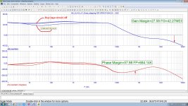
In fact, the output resistance of the common emitter cascade (open collector) is more than a megaohm, and the reason for the increase in the loop gain at medium and high frequencies is the lowering of the impedance of my T-shaped RIAA at frequencies near 7950 µs. I attach a loopgain prooflink with stepping of 7950 resistor (R19), - without it a dimple @ 20 Hz disappears.the open-loop output impedance of your amplifier must be about 20 kohm, so it is not >> the feedback network input impedance at low frequencies. That probably explains the loop gain increase you see between 40 Hz and 10 kHz in post #116.
PS. Thanks for your bi-fet input explanation, I agree that it is better -3 dB noise penalty of differential pair but without a headache of single-ended input power supply. Your original circuit design is something between a differential stage and a single stage, but without the show-offs with the power supply
Attachments
Last edited:
1 Meg not amp but naked output common emitter stage without feedback loop. With FB loop closed 10k load (with series 470 output resistor) shunts resistors in T-shaped RIAA (68k +8k2) appox. on 18 dB, but DC servo with not too big RC restores about half. I use Microcap12 [ https://archive.org/details/mc12cd_202110 ] to simulate precisely. See here [ https://photos.app.goo.gl/JdQiD3SfqamUgYzD8 ] how DC servo works @ < 20 HzIf your amplifier has a 1 Mohm open-loop output resistance
Last edited:
1 Meg not amp but naked output common emitter stage without feedback loop.
I thought so, that's why I referred to it as the "open-loop output resistance".
With FB loop closed 10k load (with series 470 output resistor) shunts resistors in T-shaped RIAA (68k +8k2) appox. on 18 dB, but DC servo with not too big RC restores about half.
I thought you were referring to this circuit:
Are you? If so, what DC servo?
It combines nicely with the Hoeffelman and Meys feedback configuration with electrically cold input resistance. (...) My subsonic filter messes things up, though. (...) Maybe you could largely solve it by connecting R11 to the buffered output.
I've just added an updated schematic to post #1. It's not suitable for op-amps.
I've seen a commercial preamp (Yamaha C4) that made an electrically cold input resistance from an op-amp, but it used another op-amp and another RIAA in the reverse path. Not very elegant, but it was the 1980s.
All good fortune,
Chris
All good fortune,
Chris
No, newer version from here, 3rd picture [ https://imrad-com-ua.translate.goog..._sl=ru&_x_tr_tl=en&_x_tr_hl=ru&_x_tr_pto=wapp ] , you may remember previous, in which the DC servo was connected to the output stage [ https://c10.patreonusercontent.com/4/patreon-media/p/post/64952825/60afdf1a555b4d63814dd26f093959e2/eyJxIjoxMDAsIndlYnAiOjB9/1.jpg?token-time=1744156800&token-hash=MgX-ppgt8QHq_7pzYghRdfTTKwspYHhLhgtxWJ-Fna0= ] and had a limited range of offset adjustment. You then recommended (a couple of years ago) that I move the servo output to the input jfet.I thought you were referring to this circuit ( If so, what DC servo? ) :
Last edited:
It isI've seen a commercial preamp (Yamaha C4) that made an electrically cold input resistance from an op-amp
I also refused from microcircuit op-amps in the phono preamplifier, firstly because the JFE2140 with 0.9 nV/rootHz is much better than any of the fet-input op-amps, and secondly, not a single op-amp has a transadmittance output @ class A with enough current to drive both RIAA FB network and loadI've just added an updated schematic to post #1. It's not suitable for op-amps.
As an aside, who is actually using MM cartridges in this group? I haven't used one in seemingly 50 years. I am now using MC's connected in the current input mode.
I have built numerous phono stages for use with MM cartridges for friends over the years, some reasonably good, hence this is interesting. Yet can MM's get near the absolute performance of a MC? Surpass them?
I have built numerous phono stages for use with MM cartridges for friends over the years, some reasonably good, hence this is interesting. Yet can MM's get near the absolute performance of a MC? Surpass them?
@Nick Sukhov - The few operational transconductance amplifier ICs are designed for variable transconductance. We want low distortion at fixed transconductance.
@Hierfi - Records played on my AT440ML sound nearly indistinguishable from CDs of the same material.
Ed
@Hierfi - Records played on my AT440ML sound nearly indistinguishable from CDs of the same material.
Ed
I know CA3080, LM13700, MAX435/6 - obsolete, and OPA860/61 but all of them have THD near -50 dB, not less -60 dB. Too bad. Do you know better?The few operational transconductance amplifier ICs are designed
@Nick Sukhov - I don't know of better ones. Variable transconductance requires non-linearity. The problem being solved is different.
Ed
Ed
I know CA3080, LM13700, MAX435/6 - obsolete, and OPA860/61 but all of them have THD near -50 dB, not less -60 dB. Too bad. Do you know better?
In order to minimize the THD in transconductance amplifiers like an AD844 requires a feedback loop around what is effectively an input buffer stage. In the most basic form without concern for other factors:


As an aside, who is actually using MM cartridges in this group?
I am.
I have built numerous phono stages for use with MM cartridges for friends over the years, some reasonably good, hence this is interesting. Yet can MM's get near the absolute performance of a MC? Surpass them?
I have no idea. I do know that some people (Hans van Maanen, Steven van Raalte, Bob Cordell, Nick Sukhov, billshurv, possibly Hans Polak, and many others) have done experiments with non-standard cartridge loading and/or reverse resonance filters (biquads) to improve the high-frequency behaviour and transient response of moving-magnet cartridges.
No, newer version from here, 3rd picture [ https://imrad-com-ua.translate.goog..._sl=ru&_x_tr_tl=en&_x_tr_hl=ru&_x_tr_pto=wapp ] ,
I get this as third picture. It doesn't help much.
A very low impedance cartridge still has the geometric losses due to stylus non-zero dimensions and the vinyl compliance x ETM resonance (plus other cantilever wobbles) in its transfer curve, and with no easy method of (at least partial) correction.
I suspect that MC cartridges appeal to us in our mid years, when the sparkling top octave helps to make up for some of our age related hearing losses. Beyond those middle years it doesn't seem to matter anymore IME. Just a hypothesis.
All good fortune,
Chris
I suspect that MC cartridges appeal to us in our mid years, when the sparkling top octave helps to make up for some of our age related hearing losses. Beyond those middle years it doesn't seem to matter anymore IME. Just a hypothesis.
All good fortune,
Chris
the third is not from the left, but from top to bottom, here it is https://imrad.com.ua/userdata/modul.../banner/cy-xxi-v-7-karta-naprug-jpgk4s5Eh.jpgI get this as third picture. It doesn't help much.
- Home
- Source & Line
- Analogue Source
- Single-stage active RIAA correction with second- or third-order Butterworth high-pass included