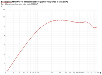
Here is the on-axis response of the driver. The mic was at 1 m distance. The time window was 4 ms. I merged the FF scan with the NF scan in accordance with VituixCad standard procedure. I adjusted the NF scan to be 4-pi equivalent using the diffraction modelling tool. I tested at a lower voltage, so I adjusted the data to be equivalent to 2.83V/1m.

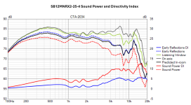
I made horizontal polar response scans from 0 - 180 degrees, in 15 degree increments. Here are the directivity and sound power/DI plots.


I did not repeat the distortion testing that I performed last summer. This data was taken in a different prototype test box, but I think it is sufficient to get an understanding of the harmonic distortion performance of this driver. I made the distortion sweep using STEPS, from 200 - 8k.


If anyone is interested, I can post this data in pdf or pptx format. I also have all of the impedance and FR scans as data files.
j.
I made horizontal polar response scans from 0 - 180 degrees, in 15 degree increments. Here are the directivity and sound power/DI plots.
I did not repeat the distortion testing that I performed last summer. This data was taken in a different prototype test box, but I think it is sufficient to get an understanding of the harmonic distortion performance of this driver. I made the distortion sweep using STEPS, from 200 - 8k.
If anyone is interested, I can post this data in pdf or pptx format. I also have all of the impedance and FR scans as data files.
j.

I was very curious about the shape of the driver response below 1k. The driver has a natural rise below 1k, and this is enhanced (exacerbated?) by the baffle shape. I wanted to see if a reasonable response could be formed with a simple network.
It turns out that it is quite easy to get a good midrange response from this SB12MNRX. The light blue dashed line is the raw driver response in the test box. The solid purple (magenta) line is a target curve consisting of 300 Hz LR2 high pass and a 3000 Hz LR2 low pass... which is a very typical response that would be useful in a 3-way system. It is fairly easy to get the driver following the target curve quite nicely from 150 Hz to 7 kHz. The network is fairly simple for a high-pass-low-pass-w/BSC crossover. I was not expecting it to be so easy.


Of course any speaker that uses this driver will need a network customized and optimized for the application, but this shows that good performance can be extracted from driver without needing a dozen components in the midrange filter.
j.
It turns out that it is quite easy to get a good midrange response from this SB12MNRX. The light blue dashed line is the raw driver response in the test box. The solid purple (magenta) line is a target curve consisting of 300 Hz LR2 high pass and a 3000 Hz LR2 low pass... which is a very typical response that would be useful in a 3-way system. It is fairly easy to get the driver following the target curve quite nicely from 150 Hz to 7 kHz. The network is fairly simple for a high-pass-low-pass-w/BSC crossover. I was not expecting it to be so easy.
Of course any speaker that uses this driver will need a network customized and optimized for the application, but this shows that good performance can be extracted from driver without needing a dozen components in the midrange filter.
j.
@hifijim - I know that I can click the "Like" button and select the "Thank You" hands, but that would not do justice. So...THANK YOU!!!
Of note, @hifijim, that 4.7 ohm resistor will get hot in that midrange circuit. The reason why is the resistor and shunt coil bypass the highpass and are essentially directly across the amplifier terminals. The bandwidth limiting that is normally in place and allows lower wattage resistors is effectively bypassed around the 68uF. This is why a CR contour as such should not be used out front with an immediate following shunt path. It should be easy enough to do this and make it fit a target without resorting to this component layout.
ah yes... I see that. I try to think like an EE, but I sometimes miss these sorts of things until later in the sim process...that 4.7 ohm resistor will get hot in that midrange circuit.
The 4.7 Ohm resistor that @wolf_teeth was speaking of had a power dissipation of 20W (28.3 Vrms pink noise). And the impedance of the midrange circuit was fixed at 4.7 Ohm at low frequencies. This would result in extremely low system impedance once the woofer was included.
Here is a more realistic network for this mid. The 5.6R has a dissipation of 5.9 W, and all other resistors are less.


Yes, this is more realistic.
If the mid needs to be padded down (I am guessing it will need about -4 dB of pad), there will be additional opportunity to increase the impedance and spread the power dissipation among more resistors. And as I said, this is all very hypothetical and very preliminary. It just demonstrates feasibility.
j.
Here is a more realistic network for this mid. The 5.6R has a dissipation of 5.9 W, and all other resistors are less.
Yes, this is more realistic.
If the mid needs to be padded down (I am guessing it will need about -4 dB of pad), there will be additional opportunity to increase the impedance and spread the power dissipation among more resistors. And as I said, this is all very hypothetical and very preliminary. It just demonstrates feasibility.
j.
Hifijim's work above is requiring me to up my game.
My measurements were to get a better high-level idea of the diffraction caused by the 16" wide baffle, but I did not build a separate midrange enclosure. I think that probably creates a few issues, but particularly relevant is my low frequency roll-off is basically the driver in free-air. But to really make a final decision on our midrange driver, and be able to make a fair comparison to Jim's measurements, I will re-measure my 3 midranges with a proper midrange enclosure, 0-180 degrees in 15 degree increments.
My measurements were to get a better high-level idea of the diffraction caused by the 16" wide baffle, but I did not build a separate midrange enclosure. I think that probably creates a few issues, but particularly relevant is my low frequency roll-off is basically the driver in free-air. But to really make a final decision on our midrange driver, and be able to make a fair comparison to Jim's measurements, I will re-measure my 3 midranges with a proper midrange enclosure, 0-180 degrees in 15 degree increments.
Jim’s documentation is 2nd to none.
Inspiring each other to doing better work is what can be great about a forum.
Inspiring each other to doing better work is what can be great about a forum.
Thanks for the kind words. @A4eaudio - I wanted to give you enough data so you could compare to the drivers you have on hand. You should only "up your game" to whatever level allows you to make a decision. As the builder of the prototype, you have a lot of decision authority.
My biggest concerns with the SB12MNRX are:
(1) It is a 4 Ohm driver, and sometimes it is difficult to manage the impedance of a 3-way passive crossover when using a 4 Ohm midrange. The fact it will probably need some padding helps.
(2) The visual impact of a 4" driver combined with a 12" woofer. It may look odd to some people, and it may limit the appeal.
j.
- Here are measurements for the Scanspeak 15W/4434G-00 and the SB Acoustics SB15MFC30-8 with a test enclosure 5-1/2 inch cubed (about 2.7L)
- I know it is a little repetitive, but I will re-post hifijim's measurements here for the SB12MNRX2 so they are together. I have tried as much as possible to use the same scales and colors.
continued...
Attachments
Here is a quick sim for the SS 15W/4434 with LR2 at 400Hz and 2.5kHz.
I don't think the SB15MFC is very easy, the dip at 1.3kHz is about 6dB deep.

I don't think the SB15MFC is very easy, the dip at 1.3kHz is about 6dB deep.
I know it has been said before by others.
Thank you A4eaudio for your tireless devotion to provide this data to the community.
It must have taken hours of your time to build, fit, measure and take all of these measurements.
Thank you A4eaudio for your tireless devotion to provide this data to the community.
It must have taken hours of your time to build, fit, measure and take all of these measurements.
Thanks for the time taken for all those measurements.
Harbeth launch the new nle-3. Nice modernization of a monkey coffin ...
12 Inch with 20cm mid (probably the basket size rather than cone) overall internal volume is about 60L. I prefer mid tweet not at center on MC. But this one is realy nice ...

Harbeth launch the new nle-3. Nice modernization of a monkey coffin ...
12 Inch with 20cm mid (probably the basket size rather than cone) overall internal volume is about 60L. I prefer mid tweet not at center on MC. But this one is realy nice ...
https://harbeth.co.uk/nle-3-loudspeaker/
Price obviously for a pair with dsp and NCore amps is 23000£

Price obviously for a pair with dsp and NCore amps is 23000£
Good to know that Harbeth offers an entry-level 3-way for the budget conscious audio consumer... 😉
Even the ol' guys at Harbet are getting on board with electrical signal correction and per-drive amplification:
8" mid- really?

Estimated cone diameter from middle of inverted surround is 120 +/-1mm 🤓
Audiophile worthy external DSP and N-Care amplifiers

Marketing at its finest.
8" mid- really?
Estimated cone diameter from middle of inverted surround is 120 +/-1mm 🤓
Audiophile worthy external DSP and N-Care amplifiers
Marketing at its finest.
- Home
- Loudspeakers
- Multi-Way
- Budget Classic 3-way Discussion Thread