excellent researchI've written something about the effect of finite op-amp gain-bandwidth product
 ! I am even more convinced that the best circuit solution for a phono preamplifier with a deep change in the frequency response of 40 dB is to ensure the constancy of the loop gain, for example, by using transadmittance RIAA correction [ example: https://photos.app.goo.gl/xcDaSEkhV7ZMJPUT6 ]
Discounting the region below the first pole, and subsonics, this is already mostly (within a few dB) true for monolythic op-amps and RIAA. But one could argue that more loop gain margin is more better if all else can be made equal. Real phono cartridges can't generate slewing rates enough to challenge any modern monolythic op-amp, so the same RIAA network used for a lossy transadmittance RIAA curve can be returned to the inverting input with the benefit of reducing input capacitance.
All good fortune,
Chris
All good fortune,
Chris
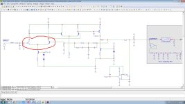
of course, you certainly know that in my phono preamplifier the transadmittance RIAA simultaneously loads the high-impedance output stage and closes the general feedback loop. = almost constant feedback loop from from tenths of a hertz to tens of kilohertz (as in attach @ #101) by the simplest means, +no Miller input capacitance (= no need to use cascode @ input)so the same RIAA network used for a lossy transadmittance RIAA curve can be returned to the inverting input with the benefit of reducing input capacitance
Last edited:
Nick, if I understand correctly, your topology takes feedback from the high impedance junction of the output of the "VAS" with the input of the output stage follower, and returns it, RIAA corrected, to the inverting input. This forces the open loop response to mimic the RIAA curve because open loop gain is Gm x load impedance, and circuit impedances are very very high impedance compared to the RIAA feedback network. Is this correct?
Seems like a good way to build a phono equalizer with discrete parts, but difficult with monolythic op-amps. Type 5534 does have access to that junction, but may not have enough current for required slewing at likely RIAA impedances. Lipshitz values would need several milliamps peak to work at all. So, a modern folded cascode in discrete parts?
All good fortune,
Chris
Yes !Nick, if I understand correctly, your topology takes feedback from the high impedance junction of the output of the "VAS" with the input of the output stage follower, and returns it, RIAA corrected, to the inverting input.
 https://imrad-com-ua.translate.goog..._sl=ru&_x_tr_tl=en&_x_tr_hl=ru&_x_tr_pto=wapp
I do my phono preamp exactly like that - with discrete JFE2140 input and transaddmittance RIAA cor class A (15 mA !) output, - betterr than Sparcos/Burson/Orange https://photos.app.goo.gl/PsEY9fsXPhZEUhm97Seems like a good way to build a phono equalizer with discrete parts,
https://www.patreon.com/posts/gerbers-drill-cy-124728954
Last edited:
Thank you. This is indeed a single stage, but I would suggest that it operates more like an op-amp than a transadmittance amp in practice. Component values aren't shown, but to have open loop gain dominated by the RIAA network, would not the other circuit impedances, including an unspecified load, need to be much higher than the RIAA network impedances? And require an output follower to buffer the external load?
This quibble is of course no judgement about its actual performance, doubtlessly excellent. I'm, in any case, not convinced by the argument that a constant loop gain is even desirable. That was fought out in the John Curl / Bob Cordell wars of about 1980, and seemed concluded.
Slava Ukraini,
Chris
This quibble is of course no judgement about its actual performance, doubtlessly excellent. I'm, in any case, not convinced by the argument that a constant loop gain is even desirable. That was fought out in the John Curl / Bob Cordell wars of about 1980, and seemed concluded.
Slava Ukraini,
Chris
It combines nicely with the Hoeffelman and Meys feedback configuration with electrically cold input resistance. Their configuration requires an output buffer anyway, otherwise the input impedance becomes dependent on the load impedance.

My subsonic filter messes things up, though. The signal current through the output stage is no longer equal to the current through R12 (that is, the resistor from the negative input to ground that is called R12 in the schematic in post #1 and called R1 in the picture in this post, which comes from Electronics World October 2003). This is because of the path through R11 and C7. Maybe you could largely solve it by connecting R11 to the buffered output.
My subsonic filter messes things up, though. The signal current through the output stage is no longer equal to the current through R12 (that is, the resistor from the negative input to ground that is called R12 in the schematic in post #1 and called R1 in the picture in this post, which comes from Electronics World October 2003). This is because of the path through R11 and C7. Maybe you could largely solve it by connecting R11 to the buffered output.
Last edited:
Such a stages can really be called an operational transadmittance amplifier (OTA).This is indeed a single stage, but I would suggest that it operates more like an op-amp than a transadmittance amp in practice.
Yes, but according to table 13 of IEC 61938:2018 the load resistance of phono preamplifiers (or input of power amplifiers) should be >= 10 kOhm (typical powamp Rin=47...100 kOhm). This is twice the minimum resistance of lowest feedback resistor of the RIAA and much more than output resistance of preamp with closed FB loop = 15 Ohms. So the output emitter follower (outside the feedback loop) is not necessary, it will only increase THD.but to have open loop gain dominated by the RIAA network, would not the other circuit impedances, including an unspecified load, need to be much higher than the RIAA network impedances
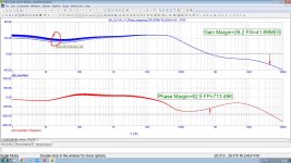
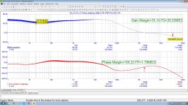
see attached Cy-XXI phonopreamp loop gain change with Rload stepping 10k...470k - it is 40 dB with 470k load and 30 dB with lowest (as IEC 61938:2018 table 13 requirements) 10k load @ 20 Hz . only -10 dB of loop gain and no FR changes . It is because I effectively use also a DC servo loop (see Marcel`s research on this).Loading will affect the 20Hz gain long before the 20KHz gain.
Attachments
Last edited:
without mandatory t4=7950us most of phono preamps have +3 dB = 41% error @ 20 Hz [ https://www.diyaudio.com/community/threads/antiriaa7950.425101/#post-7955406 ], and everyone pretends that they are okay with it . I have not~3% error That is okay if one is not aiming for world-class EQ accuracy.
Ed
 41%, but maximum 3% = 0.25 dB with lowest 10k loading resistance and < 0.07 dB with 47k, significantly less than the error due to the mechanical low-frequency resonance of the tonearm
Last edited:
I expect fourI expect a good pre-amp to implement the three RIAA time constant
I suddenly realized a nuance regarding your remark. The thing is that my MM phono preamplifier has the gain at 1 kHz set to the default +49 dB [ second graph here https://imrad-com-ua.translate.goog..._sl=ru&_x_tr_tl=en&_x_tr_hl=ru&_x_tr_pto=wapp ], not the usual +40 dB (in order to avoid the need for an extra Linear amplifier between phono out and the power amplifier input). But if I set the gain @1k to 40 dB, the loop gain curve at 20 Hz will look like what you would probably like: +38 dB at a 10 kOhm load and 47 dB at a 470 kOhm load. How do you like that?30dB of loop gain is ~3% error. That is okay if one is not aiming for world-class EQ accuracy.
Attachments
Last edited:
I guess your feedback network input impedance is around 18 kohm at 20 Hz then (*). That's quite low.
In the mid-1990's it was difficult to get precision capacitors above 10 nF, so it was attractive to use higher impedances so you didn't have to connect many small precision capacitors in parallel. That may not be applicable anymore now that there are multilayer NP0/C0G capacitors.
(*): I'm assuming that the open-loop output impedance of the active part is much greater than the feedback network input impedance, as implied by your earlier posts; if that doesn't hold anymore at 20 Hz, the feedback network input impedance may be higher. In the end, the open-loop output impedance in parallel with the feedback network input impedance has to be about 18 kohm.
Last edited:
@Nick Sukhov - Yes, I use 40dB of gain at 1KHz.
Ed
That is what I expect for a single op-amp.Nick Sukhov said:+38 dB at a 10 kOhm load and 47 dB at a 470 kOhm load. How do you like that?
My passive EQ impedance is also quite low, but it has gain before and after.MarcelvdG said:I guess your feedback network input impedance is around 18 kohm at 20 Hz then. That's quite low.
Ed
No, 180 Ohм to ground from the gate of the right input FET х 60 dB @ 20 Hz = 180 kOhm, not 18!I guess your feedback network input impedance is around 18 kohm at 20 Hz then.
Marcel, sorry for the off-topic, - tell me briefly what exactly attracted you to the pair of the jfet with the bipolar in your phono preamp Fig.5 EV 10/2003? I modeled the same pair for myself [ see attached ] and along with the increase in loop gain several times, I also found a penalty in noise (but I have a 6 mA DC current both for my jfet and bipolar).
Attachments
Last edited:
Then the open-loop output impedance of your amplifier must be about 20 kohm, so it is not >> the feedback network input impedance at low frequencies. That probably explains the loop gain increase you see between 40 Hz and 10 kHz in post #116.
Regarding the mixed JFET-bipolar transistor pair, are you sure you used the same transistors as I did (J310 and 2SC2547) and if so, that their noise is properly modelled? In principle, even at very low impedance levels, a JFET can always outperform a bipolar transistor at audio frequencies if it is big enough, but J310 was the biggest I could get at local electronics parts shops and I didn't want to connect a bunch of them in parallel. Tail current source noise doesn't cancel, so you also have to be careful with that.
Regarding the mixed JFET-bipolar transistor pair, are you sure you used the same transistors as I did (J310 and 2SC2547) and if so, that their noise is properly modelled? In principle, even at very low impedance levels, a JFET can always outperform a bipolar transistor at audio frequencies if it is big enough, but J310 was the biggest I could get at local electronics parts shops and I didn't want to connect a bunch of them in parallel. Tail current source noise doesn't cancel, so you also have to be careful with that.
- Home
- Source & Line
- Analogue Source
- Single-stage active RIAA correction with second- or third-order Butterworth high-pass included