
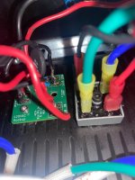
Thanks for letting me know I am definitely working on redoing the whole build with the help of @birdbox completelyIf the iec fuse holder isnt sitting flush, then you have a problem there.
Probably damaged by soldering the wires on the back pins instead of using quick connects.
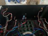
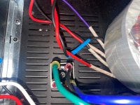
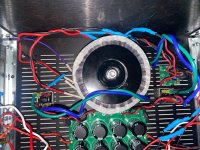
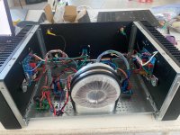
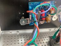
The upside down mounting of the transformer is just begging for future shorts.
I don't believe the binding posts are mounted correctly.
Looks like the insulating bushes have not been taken off and installed on either side of the panel work.
Very likely both are shorted to the case.
View attachment 1429565
Every time I try to swap out that preamp, I am left wanting. I feel I can't properly judge an amp unless it's being driven by it, single ended or balanced. I remain hopeful for a DIY effort that can match it though 🙂Fugly!
nice preamp you have there ......
The Aleph Jzm reminds me of the delicacy of an ACA, but with better diction and clarity, if that makes sense. It's pulling a lot of detail out of the Nina Simone record I'm listening to now, for example. I'd say it's on par with an F5m in that regard, but it's not quite as dynamic or thrusty so far, at least in my system.
I like this amp. As it got hotter, I kept turning the volume up, which means I like what I'm hearing. To gib the Aleph Jzm the best shot I built it single ended, even though my Aleph 20 sounded way better driven balanced. I could rewire the AJzm but that's a pain, but who knows.
Anyway, if you're a fan of either the ACA or the F5m, I recommend building this guy, it's fun.
@yarozebob
I'm going to kick off a list of items you need to consider. Please read through the Aleph Jzm build guide (and the F5m build guide) thoroughly to pick up all the great tips and tricks shared there.
I'm going to stop there as I'm sure others have much better advice. If someone want's to add to the list, please just copy the list above and keep adding on to it so we build a "to do" and "to consider" list.
First things first:
You must learn how to solder, “countless videos on YouTube”
Buy a practice solder kit or three from Amazon and practice
Proper tools. What soldering iron are you using? What type solder are you
Using?
Something like a Hakko FX-888DX Soldering Iron
Cardas or Kester solder
Use the proper accessories:
Stranded hookup wire, shielded input wire or some folks use Cat 6 ethernet
Workmanship … Assembling an amplifier and all of the sub assemblies and
it working properly on first power up is very rewarding but it can be VERY
unforgiving. Keep it neat, and clean solder residue and flux off of all
Circuit Boards. When everything is clean and wiring is tidy it is much
easier for people to help you troubleshoot any problems.
We were all in your shoes at one time and had the same problems you
are having. When your new amp that you just completed is playing your
favorite music and of course you are enjoying a cold beverage.
WHAT A RUSH
I'm going to kick off a list of items you need to consider. Please read through the Aleph Jzm build guide (and the F5m build guide) thoroughly to pick up all the great tips and tricks shared there.
- Your wiring need to be improved significantly.
- You need to be consistent with your color choices for AC line, AC nuetral, DC+, DC-, Ground, Signal+, Signal-, Output+, Output-
- The type of wire you chose is not ideal and how you're soldering it to everything is not very clean. There's a good chance of causing a short with expose wiring and heat shrink is going to be key to helping avoid shorts (aka smoke and sparks)
- Wire separation of the AC lines and the other DC and signal lines needs some real consideration or you'll have some serious hum issues. Get this right the first time and avoid the dreaded "hum hunt".
- It's clear you are new to soldering so you need to slow down and practice. Rushing here is only going to hurt you.
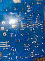
- The Amp boards look pretty rough. We can only hope that all the connections are solid, but you'll want to do a thorough quality assurance (QA) check on every single joint using a well lit and well magnified inspection.
- It's well worth practicing soldering on something else to dial in your temperature, technique, and overall quality checks.
- Safety with AC mains is of the upmost importance. This can kill if done wrong.
- You must have your safety earth well grounded to the chassis and secure so it cannot break free.
- Your AC line and neutrals need to be solid connections and well insulated so there are no exposed portions and can't be pulled loose.
I'm going to stop there as I'm sure others have much better advice. If someone want's to add to the list, please just copy the list above and keep adding on to it so we build a "to do" and "to consider" list.
First things first:
You must learn how to solder, “countless videos on YouTube”
Buy a practice solder kit or three from Amazon and practice
Proper tools. What soldering iron are you using? What type solder are you
Using?
Something like a Hakko FX-888DX Soldering Iron
Cardas or Kester solder
Use the proper accessories:
Stranded hookup wire, shielded input wire or some folks use Cat 6 ethernet
Workmanship … Assembling an amplifier and all of the sub assemblies and
it working properly on first power up is very rewarding but it can be VERY
unforgiving. Keep it neat, and clean solder residue and flux off of all
Circuit Boards. When everything is clean and wiring is tidy it is much
easier for people to help you troubleshoot any problems.
We were all in your shoes at one time and had the same problems you
are having. When your new amp that you just completed is playing your
favorite music and of course you are enjoying a cold beverage.
WHAT A RUSH
Hi I am about to reintroduce myself. My name is William i am building an Aleph J Zen Mod thank you Nelson pass And Zen Mod for this being even possible for such an amp that I haven’t heard yet but have heard so much good about even being possible to build with all of the amplifier parts being supplied in a kit. Thank you again.
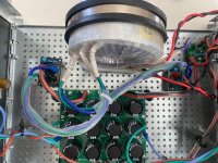
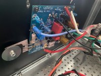
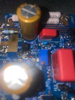
I will say the first time I wire the amp and power supply up it wasn’t done very good messy and lack of soldering experience so a lot of ugly soldering jobs even now my boards don’t look to nice. Also before someone points it out and judges me 😭 yes I drilled the holes on the back plate myself(didn’t know I could just get the deluxe 4u chassis from modushop) and I didn’t know what the heck I was doing with the jigsaw so PEM cutout looks terrible.
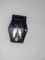
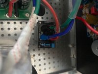
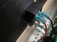
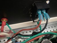
The first time I plugged the amp in i had no power whatsoever. This is why you shouldn’t try to solder any wire except maybe the ground into a PEM(photo attached).That prevented me from getting any power and I learned that because i measured ac connecting red and black probes on line and neutral side for mains as well as the switch connections and realized I was not getting 120v at the side of the switch that goes to the 120v in for the power supply
I will say the first time I wire the amp and power supply up it wasn’t done very good messy and lack of soldering experience so a lot of ugly soldering jobs even now my boards don’t look to nice. Also before someone points it out and judges me 😭 yes I drilled the holes on the back plate myself(didn’t know I could just get the deluxe 4u chassis from modushop) and I didn’t know what the heck I was doing with the jigsaw so PEM cutout looks terrible.
The first time I plugged the amp in i had no power whatsoever. This is why you shouldn’t try to solder any wire except maybe the ground into a PEM(photo attached).That prevented me from getting any power and I learned that because i measured ac connecting red and black probes on line and neutral side for mains as well as the switch connections and realized I was not getting 120v at the side of the switch that goes to the 120v in for the power supply
Attachments
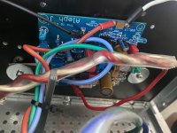
I apologize not great pictures. These are pics of the first build I know pretty bad. Wires spliced together globs of solder some stuff probably not wired correctly i had to re do all of this get more tools(had cheap soldering iron now i have a weller as of yesterday, heat gun is coming(used other forms of heat prior which were not to great), and other tools and thanks to @birdbox many useful connectors and wiring which I am thankful and appreciate to him for.

Attachments
-
 IMG_0275.jpeg915.2 KB · Views: 37
 -
 IMG_0274.jpeg856.9 KB · Views: 37
 -
 IMG_0273.jpeg702.9 KB · Views: 38
 -
 IMG_0272.jpeg674 KB · Views: 37
 -
 IMG_0271.jpeg717.4 KB · Views: 40
 -
 IMG_0270.jpeg768 KB · Views: 33
 -
 IMG_0269.jpeg706.3 KB · Views: 45
 -
 IMG_0266.jpeg857.2 KB · Views: 46
 -
 IMG_0265.jpeg988.3 KB · Views: 48
 -
 IMG_0264.jpeg966.1 KB · Views: 44
 -
 IMG_0263.jpeg814.6 KB · Views: 37
 -
 IMG_0267.jpeg1.1 MB · Views: 40
 -
 IMG_0268.jpeg1.1 MB · Views: 44
Hi William -
First, congratulations on taking the leap into trying to build the AJzm. Second, kudos for showing your build and sharing your experience even it it wasn't perfect. As you've seen, the community here is fantastic. You'll have a working project in no time. It's fantastic that you didn't just quit when you had an issue. You asked for some help, and you'll get a lot of it.
In the interim, if you need any of the parts for the kit, just let me know. I'll send them your way.
The next project will go more smoothly ... and then the next ... and then the next.
Let us know when you're listening to beautiful music.
Cheers,
Patrick
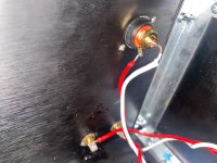
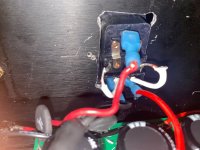
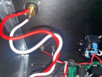
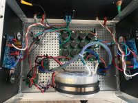
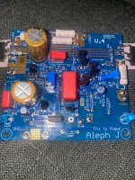
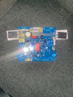
Photos of recent build. I am trying to learn to take better pictures so please help me with useful feedback on how to improve my photo taking
Attachments
-
 IMG_0302.jpeg908.9 KB · Views: 39
 -
 IMG_0301.jpeg957.5 KB · Views: 45
 -
 IMG_0342.jpeg883.7 KB · Views: 38
 -
 IMG_0305.jpeg1,009.7 KB · Views: 42
 -
 IMG_0306.jpeg1 MB · Views: 39
 -
 IMG_0309.jpeg926.9 KB · Views: 44
 -
 IMG_0310.jpeg1 MB · Views: 52
 -
 IMG_0311.jpeg865.1 KB · Views: 43
 -
 IMG_0312.jpeg846.2 KB · Views: 40
 -
 IMG_0313.jpeg979.2 KB · Views: 41
 -
 IMG_0314.jpeg897 KB · Views: 34
 -
 IMG_0315.jpeg731.9 KB · Views: 39
 -
 IMG_0316.jpeg858.6 KB · Views: 37
 -
 IMG_0317.jpeg738.7 KB · Views: 34
 -
 IMG_0318.jpeg705.8 KB · Views: 43
Thank you you all are very encouraging. And I definitely willHi William -
First, congratulations on taking the leap into trying to build the AJzm. Second, kudos for showing your build and sharing your experience even it it wasn't perfect. As you've seen, the community here is fantastic. You'll have a working project in no time. It's fantastic that you didn't just quit when you had an issue. You asked for some help, and you'll get a lot of it.
In the interim, if you need any of the parts for the kit, just let me know. I'll send them your way.
The next project will go more smoothly ... and then the next ... and then the next.
Let us know when you're listening to beautiful music.
Cheers,
Patrick
Attachments
-
 IMG_0309.jpeg926.9 KB · Views: 37
 -
 IMG_0306.jpeg1 MB · Views: 34
 -
 IMG_0305.jpeg1,009.7 KB · Views: 34
 -
 IMG_0310.jpeg1 MB · Views: 30
 -
 IMG_0311.jpeg865.1 KB · Views: 25
 -
 IMG_0312.jpeg846.2 KB · Views: 26
 -
 IMG_0313.jpeg979.2 KB · Views: 31
 -
 IMG_0314.jpeg897 KB · Views: 30
 -
 IMG_0315.jpeg731.9 KB · Views: 25
 -
 IMG_0316.jpeg858.6 KB · Views: 25
 -
 IMG_0317.jpeg738.7 KB · Views: 26
 -
 IMG_0318.jpeg705.8 KB · Views: 29
 -
 IMG_0307.jpeg928.2 KB · Views: 45
 -
 IMG_0308.jpeg866.3 KB · Views: 38
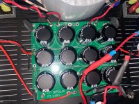
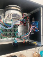
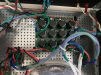
Now here is t my Dilenma now my boards are now powered up and and did tests with my multi meter:
120v ac to switch check
120v ac to power in check
V+\V- dc to ground 24-25v check
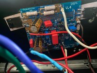
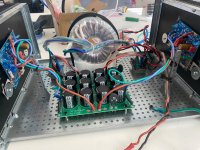
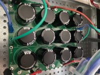
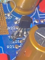
So I hook up the amp boards: JUST BUILD A DIM BULB TESTER it’s CHEAP OR YOU MIGHT GET MAGIC SMOKE and that’s exactly what I got. I made a bad mistake and hope i didn’t destroy my Amp boards. Replaced R27 in one of the boards because it was out of spec i probably burned it and put in R26 for good measure i attached photos showing the new resistors in. their sitting tall on the board temporarily because i had difficulty putting them in because of the residual solder in the holes. The replacements did not make the board work . Again IF YOUR A BEGINNER ASSUME YOU DID EVERYTHING PERFECT AND DONT USE A DIM BULB TESTER OR ELSE SMOKE. Today l i ordered the stuff to make a DBT and I’m just waiting for everything to come. In the meantime if anybody can help me with what I may have done wrong is there a short or something improperly soldered or what should I test and how to figure out what’s going on.
120v ac to switch check
120v ac to power in check
V+\V- dc to ground 24-25v check
So I hook up the amp boards: JUST BUILD A DIM BULB TESTER it’s CHEAP OR YOU MIGHT GET MAGIC SMOKE and that’s exactly what I got. I made a bad mistake and hope i didn’t destroy my Amp boards. Replaced R27 in one of the boards because it was out of spec i probably burned it and put in R26 for good measure i attached photos showing the new resistors in. their sitting tall on the board temporarily because i had difficulty putting them in because of the residual solder in the holes. The replacements did not make the board work . Again IF YOUR A BEGINNER ASSUME YOU DID EVERYTHING PERFECT AND DONT USE A DIM BULB TESTER OR ELSE SMOKE. Today l i ordered the stuff to make a DBT and I’m just waiting for everything to come. In the meantime if anybody can help me with what I may have done wrong is there a short or something improperly soldered or what should I test and how to figure out what’s going on.
Attachments
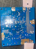

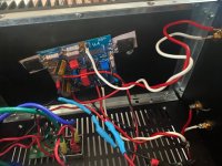
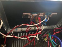
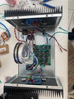
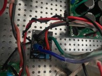
is there enough clearance between pcbs and heatsink, to avoid shorts?
confirmed with ohmmeter?
I don’t think the solder joints on the boards are touching the heat sink. should I install standoffs? Also how would I test that with ohmmeteris there enough clearance between pcbs and heatsink, to avoid shorts?
confirmed with ohmmeter?
Just a couple of tips.. you will want to trim your component leads after the soldering process. Only trim the excess component lead that is sticking up. Don't cut down into the actual solder joint itself, also called the solder fillet.
In nearly all situations you would want your PCB's mounted on standoffs. The power MOSFETs would be the very last thing you solder. Meaning you form the FET leads how they need to be, and mount that part onto the heatsink. The completed PCB (minus the power FETs obviously) then gets laid onto the FET leads and lined up with the standoffs that you would have pre-installed into the heatsink. It should all fit together perfectly if you do it right. With the PCB now secured to the standoffs with the hardware, you can finally solder the power MOSFETs. There's probably a section in one of the build guides explaining and showing the steps more clearly.
In nearly all situations you would want your PCB's mounted on standoffs. The power MOSFETs would be the very last thing you solder. Meaning you form the FET leads how they need to be, and mount that part onto the heatsink. The completed PCB (minus the power FETs obviously) then gets laid onto the FET leads and lined up with the standoffs that you would have pre-installed into the heatsink. It should all fit together perfectly if you do it right. With the PCB now secured to the standoffs with the hardware, you can finally solder the power MOSFETs. There's probably a section in one of the build guides explaining and showing the steps more clearly.
Attachments

as I see it, best and fastest way of doing it, considering your lack of adequate mileage is - invest some efforts to find lending hand in your neck of wood
we all started somewhere in time, with something new; in most cases least panful way is to start with actual Tutor, even if just for few lectures
we all started somewhere in time, with something new; in most cases least panful way is to start with actual Tutor, even if just for few lectures
There's probably a section in one of the build guides explaining and showing the steps more clearly.
Patrick IAIMH invested substantial efforts to cover practically everything in his Build Guide, especially to produce pictures, each worth 3000 words
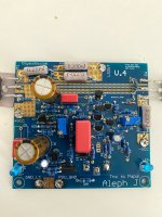
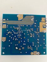
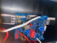
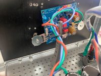
I know t4 looks funny because I installed it backwards and had some issue trying to remove it and reinstall(unfortunately that happened to both boards I will try to clean it up
if you did measure 20V across R29, that means plenty of things can be Dodo
though, you need to clarify your word "at"
as it is, there is -22Vsomething at one side of it, that being negative rail, while at the other side of it is, say, 500mV less; all that ref. to GND, meaning black probe on GND potential
though, you need to clarify your word "at"
as it is, there is -22Vsomething at one side of it, that being negative rail, while at the other side of it is, say, 500mV less; all that ref. to GND, meaning black probe on GND potential
- Home
- Amplifiers
- Pass Labs
- Aleph Jzm