I'd like to present my project of power amplifier with novelty (I hope) gain-frequency compensation, and some other tricks resulting with high amplifier gain and very low THD.
Everybody knows most common method of making amplifier stable – it is Miller compensation: capacitor put between output and inverting input of amplifier (across one or more of amplifier’s stages). This simply puts dominant pole at very low frequency producing well known phase-amplitude open loop response of the amplifier, when high gain is flat to frequencies at most hundreds of Hertz (first, dominant pole), and then fall monotonically in 6dB per octave till unity gain.
My solution allows for very high and almost flat gain till almost 1 kilohertz, and then steep but controlled slope and phase till unity gain, where phase margin is above 45 degrees, and Nyquist stability criteria is fully met, even with capacitive load.
Compensation is done by a low pass filter between amplifier's stages with one pole and one zero. This is enough to make amplifier stable, but to increase phase margin I've added small forward compensation and also small Miller compensation with pole beyond low pass filter and zero before unity gain.
All amplifier design is kept as simple as possible, without unnecessary items (like mosfet drivers). I've only left resistors in MOSFET's sources, but only for further shortcut/overcurrent protection.
Finally I’ve got these numbers:
100W 8 Ohm.
115dB maximum open loop gain (with feedback network, amplifier alone has 147dB gain), first pole at 800Hz
111dB gain at 1kHz
92dB gain at 10kHz
Closed loop gain 32dB (40V/V)
Slew rate 47V/us
10MHz unity gain, with phase margin 62 degree and amplitude margin 10dB
1W 1kHz THD=0,000007%
100W 1kHz THD=0.000035%
Thermal stability (-12% quiescent current at 150 degree Celsius)
NOTE: this is so far LTSpice simulation, but I’ve choosen pats which are cheap, still in production and available everywhere. I’m going to make this amplifier and test it.
Here are some pictures,
Phase-amplitude characteristics

And this same with capacitive load

THD numbers for 1W 1kHz

Fourier for 1kHz 1W

Intermodulation FFT (9kHz+10kHz 8Vpp out)

LTspice do not shows much, so I've put numbers to Excel and produce more legible graph (horizontally kilohertz, vertically dB)

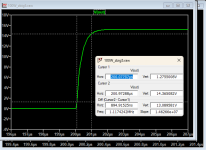
Step response with overdrive. As you see it lasts less than microsecond to stabilize output level

This same step but with input low pass filter (no overdrive with full power 10kHz square wave)

Noise figure

Thermal stability

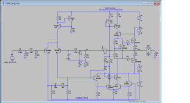
And finally schematics

This is not a final version, and some improvements should be done, e.g. increase clipping output voltage, and gate protection.
Everybody knows most common method of making amplifier stable – it is Miller compensation: capacitor put between output and inverting input of amplifier (across one or more of amplifier’s stages). This simply puts dominant pole at very low frequency producing well known phase-amplitude open loop response of the amplifier, when high gain is flat to frequencies at most hundreds of Hertz (first, dominant pole), and then fall monotonically in 6dB per octave till unity gain.
My solution allows for very high and almost flat gain till almost 1 kilohertz, and then steep but controlled slope and phase till unity gain, where phase margin is above 45 degrees, and Nyquist stability criteria is fully met, even with capacitive load.
Compensation is done by a low pass filter between amplifier's stages with one pole and one zero. This is enough to make amplifier stable, but to increase phase margin I've added small forward compensation and also small Miller compensation with pole beyond low pass filter and zero before unity gain.
All amplifier design is kept as simple as possible, without unnecessary items (like mosfet drivers). I've only left resistors in MOSFET's sources, but only for further shortcut/overcurrent protection.
Finally I’ve got these numbers:
100W 8 Ohm.
115dB maximum open loop gain (with feedback network, amplifier alone has 147dB gain), first pole at 800Hz
111dB gain at 1kHz
92dB gain at 10kHz
Closed loop gain 32dB (40V/V)
Slew rate 47V/us
10MHz unity gain, with phase margin 62 degree and amplitude margin 10dB
1W 1kHz THD=0,000007%
100W 1kHz THD=0.000035%
Thermal stability (-12% quiescent current at 150 degree Celsius)
NOTE: this is so far LTSpice simulation, but I’ve choosen pats which are cheap, still in production and available everywhere. I’m going to make this amplifier and test it.
Here are some pictures,
Phase-amplitude characteristics
And this same with capacitive load
THD numbers for 1W 1kHz
Fourier for 1kHz 1W
Intermodulation FFT (9kHz+10kHz 8Vpp out)
LTspice do not shows much, so I've put numbers to Excel and produce more legible graph (horizontally kilohertz, vertically dB)
Step response with overdrive. As you see it lasts less than microsecond to stabilize output level
This same step but with input low pass filter (no overdrive with full power 10kHz square wave)
Noise figure
Thermal stability
And finally schematics
This is not a final version, and some improvements should be done, e.g. increase clipping output voltage, and gate protection.
Attachments

You have to prove your solution is better than TMC(Transitional Miller Compensation). TMC is the gold standard of compensation with more than single pole. Simple and effective.
Yes, MTC compensation is simple and effective. But also with drawbacks. If you want to achieve high gain but stable at unity gain, you need to set first pole at very low frequency (due to -6dB/octave slope), which is counter-productive, because you still get low gain at medium frequency. Unless you'll build amplifier with very high bandwidth (but this is hard to achieve with high voltage/high current transistors, especially power ones).
My solution allows for steeper slope than -6dB/octave, and thus higher gain at mid frequencies.
Compare these two graphs: This same amplifier with classic MTC,

and with ONLY my compensation method (no Miller at all)

My solution allows for steeper slope than -6dB/octave, and thus higher gain at mid frequencies.
Compare these two graphs: This same amplifier with classic MTC,
and with ONLY my compensation method (no Miller at all)
Last edited:
For TMC, you should probe the NFB around the output stage only, not for the entire amp.
One of the my project:


One of the my project:
You mean C1,C3,R4 - but this is not a classic TMC, and this as I suppose introduces also one zero. Btw. think about causes of this phase drop till 10 degree at 100kHz. It is not only TMC impact. Anyway it is interesting, although completely different. My solution do not use NFB.For TMC, you should probe the NFB around the output stage only, not for the entire amp.
Btw. I'm using modified Miller (similar, but different than yours) in my other design, which performs better than "classic" TMC
Anyway, this thread is not about how to use TMC but rather how to NOT use it ;-)
Last edited:
You can find more abouth TMC and TPC here: https://www.diyaudio.com/community/threads/tmc-or-tpc-my-dilemma-resolved.188133/#post-2556574
What these have to do with my method without NFB? These are both NFB compensations.You can find more abouth TMC and TPC here: (...)
I'm talking about method of compensation without capacitor in NFB (Miller compensation), not NFB in general.
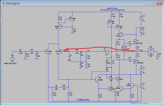
Look at this picture: there is no NFB here.

Look at this picture: there is no NFB here.
The compensation at the LTP output is well known.
The best explanation I know is there:
https://blog.easychipamp.com/2021/02/audio-amplifier-feedback-ltp-with.html
The best explanation I know is there:
https://blog.easychipamp.com/2021/02/audio-amplifier-feedback-ltp-with.html
Cause for celebration is one way to look at it. It means you're sharp and firing on all cylinders 
So let's try something else. Maybe this is fresh idea. Replacing resistors with active, balanced load we can increase open loop gain from 115dB into 124dB, and reduce THD more than twice.


And all this with this trick:

And all this with this trick:
Why perfectly matched? The most unmatched transistors are already NMOS and PMOS on output stage. Without serious impact on amp characteristics.
Good idea may be to match input transistors by its gain, to minimize output offset, but rest of them do not need to be matched.
Good idea may be to match input transistors by its gain, to minimize output offset, but rest of them do not need to be matched.
The idea of this type of compensation with a "phase boost" reminds me of Venerables excellent papers concerning switch mode power supply stabilisation using a type III compensation network. May be interesting, but new only in the audio world.
Last edited:
Good to know you also know this formula.Ic = Is * exp (Vbe/Vt)
Q4 and Q17 have the same Vbe. Ic will vary with Is and temperature (which is part of Vt). Current mirrors need emitter resistors to reduce the sensitivity of Ic to Is and temperature.
Ed
The only current mirror on my schematics has emitter resistors, namely R3 and R6.
You mean Q13 not Q17.
Why Q4 and Q13 do not need to have this same Vbe?
Short answer is this: because they are not in input stage and amplifier has very high gain with strong NFB.
And as you can see on temperature graph I've posted earlier amplifier has very good temperature stability. And even two completely different transistors changes nothing.
Interesting idea about modified Nyquist plot.
Especially our amplifiers have huge gain, and zooming Nyquist plot to reach unity circle level takes some time, and also requires manual drawing of this circle.
It is how Nyquist diagram looks for my amplifier. LTSpice should have option to do it automatically.

Especially our amplifiers have huge gain, and zooming Nyquist plot to reach unity circle level takes some time, and also requires manual drawing of this circle.
It is how Nyquist diagram looks for my amplifier. LTSpice should have option to do it automatically.
Last edited:
- Home
- Amplifiers
- Solid State
- Power amp design by Zbig with new compensation method