If you check, I have not used the term "obsessed".@jaddie, the fact that you think I'm "obsessed' shows you have some strange bias against my goal. I do appreciate your expertise though, so thank you for that but it's difficult to take you seriously when you make such outlandish statements.... I'm simply here to gain a better understanding and I have accomplished that so far. Not tryin' to throw shade your way.
You may object to me using analog but that is the scope of my question. Understanding the voltage going into the amp is very basic/core knowledge and not obsessive 😉 You learned at one time about this did you not? You sassy.
I'm not biased against your goals because I don't know what they are. Still.
Sometimes it's worth while to investigte what seem to be outlandish statements to see if they might just be true. For example, have a look at any mixers gain structure diagram, and find any stage that is unity gain. Any stage at all.
I don't object to you using analog anything, nor do I object to anyone using analog anything. I use analog stuff myself. The disconnect is in thinking that analog is somehow more pure than an equivalent digial system. It might be, but these days, it's more likely not. If you like I can comploetely explain the science of both, but I'm not getting into an analog vs digital debate. What I find is the "analog purist" belief system is a comfortable one, and people with it don't like to have their comfort challenged, even if science has some understanding to offer. That's perfectly fine, but doesn't promote growth, does it?
Please apologize but some things are just nitpicking.
I mean, UG is commonly used because once gain are dialed in even if they follow a path in which they are attenuated and boosted, in the end you got same output level in and out the board.
Of course it's not a hard bypass but still... i could go on about faders: in a 4000E/G there is no signal through the fader so they are not attenuating or boosting, the 2150 does it's job whatever and iirc they are setup to work at unity before they hit the summing bus ( if you keep dynamic section bypassed)... 9098 is on that scheme too... but AMS/Neve use 'real' faders and vca...there is too many desk over too large a period to explain all this with general description imho.
All you say is technically right but to be blunt, RoboDna didn't know how to set up input gain on a desk, don't you think going this far into details is going to help him understand the issue he face? Or will it be confusing?
Last edited:
If you check, I have not used the term "obsessed".
I'm not biased against your goals because I don't know what they are. Still.
Sometimes it's worth while to investigte what seem to be outlandish statements to see if they might just be true. For example, have a look at any mixers gain structure diagram, and find any stage that is unity gain. Any stage at all.
I don't object to you using analog anything, nor do I object to anyone using analog anything. I use analog stuff myself. The disconnect is in thinking that analog is somehow more pure than an equivalent digial system. It might be, but these days, it's more likely not. If you like I can comploetely explain the science of both, but I'm not getting into an analog vs digital debate. What I find is the "analog purist" belief system is a comfortable one, and people with it don't like to have their comfort challenged, even if science has some understanding to offer. That's perfectly fine, but doesn't promote growth, does it?
@jaddie Did you not just post "He seems obsessed with the output voltage of his desk. A simple pad fixes that." in post #62? I'm not upset about it, and I do appreciate your input big time. Can you confirm you did post that so I know I"m not seeing things?
My goal is to feed the optimal voltage into the amp from my mixer. Very easy to understand that so not sure how I can make it more clear. I've learned this involves well configured gain structure, understanding dBu, dBVU, dBV, and monitoring and protecting from clipping but again, realize I'm JUST LEARNING THIS NOW! I totally understand if it does not make sense to your expert eyes.... It's simple... need optimal voltage into amp...
I have absolutely no desire to have the analog-digital debate in any way whatsoever as it is played out big time. I find it odd that someone with expertise would bring this up... WTF, don't you know better??? hahahaha!
Here is how I handle the digital/analog debate. If you have $10,000 of analog synths/drum machines, what is your recommendation on getting that signal out to the speaker without any digital in the path? You can argue no one will notice the analog signal over a digital one, but that is NOT the question/problem. I have Wharfedale Super Lintons, the F5m Class A and the analog soundcraft mixer. That is my best setup idea. What is yours? The answers often come back with some digital piece in the path, with attempts to steer me away from using pure analog for whatever reason, which I find hilarious. ( happens all the time ) I think Neil Young, Jack White and many others run into this all the time and still spend a fortune on analog. Jack White has some weird DIY contraption to record analog and visited a sewing machine shop to get parts to fix it one time. Before I built my Class A, I shopped for an amp and speaker for my ANALOG synth and even roland recommended a digital class D amp. It's like recommending an digital amp for an electric guitar. I'm also in a home studio setting and don't need a PA or loud class D in my house.
Anyways I don't want to bog down on the digital analog debate as it is clouding my thoughts on understanding the input signal for the my amp. Also keep in mind this is a 'side project' for me and I just need to learn enough to run my amp with well configured gain stage/structure, but not become an expert like you and others who have helped me here.
If you also have analog synths, than we are for sure not very far apart on any of this stuff 🙂 What I've learned from this post alone will help me for years to come.
Last edited:
@jaddie just reading over the info. and it's a bit advanced for my level, but I do understand some of it... what do you mean by "For example, have a look at any mixers gain structure diagram, and find any stage that is unity gain. Any stage at all."
Does a good gain structure get as close to unity gain as possible? I'm thinking if the master fader is at 0dBu, than voltage is at 1.23Vrms ( unity gain ? ) If I only have 1 channel as input, I would set the master and channels' fader to 0, enable SPL for that channel so I can see the output to the VU meter, play a 1kHz sine wave and adjust the channels' gain knob so the VU Meter is peaking at ~0dBu. If you mean there is no real-world scenario where an input will not require gain or attenuation before making it to the amp, than I understand.
Does a good gain structure get as close to unity gain as possible? I'm thinking if the master fader is at 0dBu, than voltage is at 1.23Vrms ( unity gain ? ) If I only have 1 channel as input, I would set the master and channels' fader to 0, enable SPL for that channel so I can see the output to the VU meter, play a 1kHz sine wave and adjust the channels' gain knob so the VU Meter is peaking at ~0dBu. If you mean there is no real-world scenario where an input will not require gain or attenuation before making it to the amp, than I understand.
You don’t want unity gain. You want enough gain at the input to normalize the level from that device, then you want higher or lower gain per channel depending on the desired mix.
Forget about unity gain. It isn’t an objective. This is still a level matching problem and you can solve it with an attenuating pad as stated above.
Forget about unity gain. It isn’t an objective. This is still a level matching problem and you can solve it with an attenuating pad as stated above.
With faders at “0” you don’t actually have unity gain. A fader is a potentiometer that can only attenuate. “0” is an actually -12dB (if the top of the fader travel is 12dB). That fader position is actually a loss and is made up by an amplifier that follows it with 12dB of gain. Same with the master and subs. Even with everything set to zero nothing is really at unity gain, even though the whole mixer end to end seems like it is. And your channel input gain is what you use to allow the faders to operate at the most convenient position - usually zero, but not always. The input gain is whatever you need, and with synths, won’t be at unity either.@jaddie just reading over the info. and it's a bit advanced for my level, but I do understand some of it... what do you mean by "For example, have a look at any mixers gain structure diagram, and find any stage that is unity gain. Any stage at all."
Does a good gain structure get as close to unity gain as possible? I'm thinking if the master fader is at 0dBu, than voltage is at 1.23Vrms ( unity gain ? ) If I only have 1 channel as input, I would set the master and channels' fader to 0, enable SPL for that channel so I can see the output to the VU meter, play a 1kHz sine wave and adjust the channels' gain knob so the VU Meter is peaking at ~0dBu. If you mean there is no real-world scenario where an input will not require gain or attenuation before making it to the amp, than I understand.
I’m just trying to help you understand that the concept of unity gain as a sweet spot is overblown by people who may not understand what’s going on under the hood.
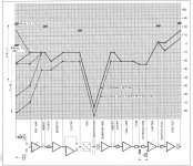
A gain structure diagram shows all the gains and losses in a mixer. I have one in a service manual here, if I get time I’ll scan and post it so you can see what I’m talking about.

Here's a gain diagram for a Studer 169 desk. It happens to be a manual I have on hand, having rebuilt one of these. To read, pick a point on the line, and read to the right (signal flow is left to right). Note the difference in level between two points, the difference in dB indicates the amount of gain or loss in that stage. Unity gain is represented by a horizontal line. You will see horizontal lines at insert points (send and return are at the same level unless a device is inserted), and at faders on the maximum gain plot (because they're all the way up), and at an isolation amp. The horizontal gain line at the filter is a little misleading because if you use any EQ, it's no longer flat, but is here shown with no EQ applied. Note that the gain/loss is up and down through the entire signal path. If it were truely "unity gain", that would have been a level horizontal line from left to right.
I realize this isn't your mixer, and mixers vary, but they all do something similar. None would ever plot a straight horizontal line in a gain plot.
I realize this isn't your mixer, and mixers vary, but they all do something similar. None would ever plot a straight horizontal line in a gain plot.
Attachments
Getting back to your pad, since the published specs on the F5m include a gain figure, but not an input sensitivity figure, we can calculate it:
At 25W into 8 ohms, the output voltage is 14.14Vrms, which is +23dBV
Gain is specified at 15.3dB, so we can subtract that from the above, and get 7.7dBV, which is the voltage required at the input for full power.
Assuming the usual 20dB of headroom for unclipped musical peaks (this depends on your music, of course), we'd need to operate 20dB below 7.7dBV, which is -12.3dBV. Typical consumer line level is -10dBV, so we're close to that.
Your mixer's specs are ambiguous as to how the meter and outputs are calibrated. And the actual output XLRs are "impedance balanced" (not true balanced) with signal on pin 2. So we treat them as unbalanced. The max output is +21.5 dBu. The question is, with the meter a "0", what's the output level? Most mixers put 0VU 20dB (or more) below maximum output. So that would put your 0VU at +1.5dBu. An odd level, and an assumption, but probably right.
To get your amp input and mixer output on the same page we have to work in the same units for both. We can use dBV. So your mixer output level, +1.5dBu is -0.7dBV. We'd like to hit the amp with -12.3dBV, so your pad is equal to the diffference of -0.7 -12.3dBV = 13dB
Given the assumption of meter calibration is correct, you'll need a 13dB pad.
Using standard 5% resistor values, 1000 ohms and 270 ohms gets you 13.45dB. One end of the 1000 ohm resistor connects to the mixer output XLR, pin 2. The other end of the 1000 ohm resistor joins the 270 ohm resistor AND the input to the power amp. The free end of the 270 gets tied to ground. And I recommend putting both resistors inside the power amp, but your choice. You could also built this pad inside of an XLRF > XLRM barrel, but since you already have an XLR > RCA cable, inside the amp might still be best for the pad.
With the pad, your actual speaker level will be controlled by your master fader, and the maximums of both the mixer and amp will be very close to the same, which maximizes signal to noise ratio, but only at one point of the system (unfortuately, proabably the least critical point).
You can buy resistors on Amazon. You'll get 50X more than you need, but they're very cheap.
^^ @jaddie This all makes sense, thanks! I'll be busy for a few days working with the mixer, and will get my oScope connected to its output. I can play a 1kHz sine to try different gain settings and confirm the output is what I expect from the math. I think I have what I need to make it all work now.
Note I made a mistake and my amp will actually output 35watts. ( I have increased the amp's bias and have larger heat sinks ). I'll re-do the math for 16.73Vrms, 24.46dBV. I see just over 16.2dB gain in the F5m guide, so if my math is correct that would be 8.26dBV minus 20dB = -11.74dBV. Hope that is right. I'm using the mixer's Group1 and Group2 outputs and not the main out. The main has a slightly higher output voltage, but like you say, I'll just treat them like unbalanced outs. The current cable I use is a TS->RCA Adapter so I'll build a cable from scratch. ( only the mixer's master out are XLR, the Groups are TS ) I can also make a 3d printed box if that is better. I rather not build it into the amp although that does sound better. I also use a focusrite i2i to connect to the amp sometimes so that would not need the pad.
Note I made a mistake and my amp will actually output 35watts. ( I have increased the amp's bias and have larger heat sinks ). I'll re-do the math for 16.73Vrms, 24.46dBV. I see just over 16.2dB gain in the F5m guide, so if my math is correct that would be 8.26dBV minus 20dB = -11.74dBV. Hope that is right. I'm using the mixer's Group1 and Group2 outputs and not the main out. The main has a slightly higher output voltage, but like you say, I'll just treat them like unbalanced outs. The current cable I use is a TS->RCA Adapter so I'll build a cable from scratch. ( only the mixer's master out are XLR, the Groups are TS ) I can also make a 3d printed box if that is better. I rather not build it into the amp although that does sound better. I also use a focusrite i2i to connect to the amp sometimes so that would not need the pad.
Some thoughts/comments:
Your scope will display peak to peak peak voltage only, not RMS. Caution.
How about adding a second set of input jacks to the amp, and a two position selector switch? One set padded, one not. You could even leave the i2i connected, and switch select between the i2i and the mixer.
3d print a box? Get a nice metal one on Amazon and go shielded.
Why do you think the group outs are a different level than the main mix? I don’t see that in the manual.
The group outs are individual, you have to pay attention to both so your l/r levels don’t go out of balance when you change them. The master/main outs are controlled with a single stereo fader and l/r levels will basically track be default.
@jaddie excellent ideas, thanks!! I'll add a second set of inputs to the amp with the pad inside the case. ( I'll need to source mouser/digikey for a switch that is suitable for audio... not sure if I should use a specific type for audio... )
Maybe I'm better off using the A/C rms setting on my digital meter instead of my scope? ( I still plan on posting a question about how to safely connect my meter/oScope to the mixer out and/or amp out since I know I can blow something )
I'll need to confirm the mixer's output voltage with a digital meter before I can re-do the calculations.
Pretty much any switch is fine in this situation, pick your favorite style. DPDT for two channel stereo.
Digital meters are typically only accurate at low frequencies, so if you use 100Hz, and it's a true RMS meter, that will be accurate enough.
Safely connecting a scope: Scopes are unbalanced, typically, so you measure from Pin 1 to Pin 2. With this mixer, that's all that matters anyway. You can use a 10X probe if you have one, but not required. Safety isn't an issue.
Measure the same points with the meter. Don't short the probes while connected, but you can't damage anything regardless.
Switch with pad is what i use on my system ( pc with multi digital out to Loudspeaker management unit( dsp) to 3 stereo amp driving in direct the 3 ways of loudspeakers): i need to be able to listen to my DAC 'potential' clipping when doing mastering work and as i use my 'mains' loudspeaker as my home domestic system too ( my living room looks more like a typical control room than a domestic room, i'm lucky my girlfriend/family tolerate this) i needed other spl range than when i work for 'home' and 'night' use.
And as i didn't want to use the digital attenuator on my system ( or for some finetuning to not loose too much resolution- dynamic range- on DAC) i used a pair of Lorlin rotary switch ( mbb) with 'calibrated' SPL range by way.
I have to turn 6 switch and then i'm good for each situation planed.
I might switch to a r2r stepped attenuator eventually but a 2x 4way is too much work and issue to solve for now...
RoboDNA it's wise to keep the pad into your amplifier case: your pad will be relatively high impedance and passive so as such they need to be located as close as possible to your amp input circuitry.
If you want to have ability to locate them more than a few centimeter away then they need some active buffer stage right after them. It complicate things a bit more as you would need a psu and some opamps. Nothing dramatically complicated but still.
Keeping a real perspective, in the pad I suggested, impedance are not high. The virtual source impedance would be around 200 ohms. With possibly the worst audio cable from a C perspective, 3 meters would have about 660pf, putting the corner frequency at 1.1MHz. And nobody uses 8451 anymore, so in all cases, the corner is actually much higher, beyond the passband of the amplifier.RoboDNA it's wise to keep the pad into your amplifier case: your pad will be relatively high impedance and passive so as such they need to be located as close as possible to your amp input circuitry.
If you want to have ability to locate them more than a few centimeter away then they need some active buffer stage right after them. It complicate things a bit more as you would need a psu and some opamps. Nothing dramatically complicated but still.
No buffer needed. And no worries about where to put the pad.
Not at all. It's a 1K build-out resistor from the console and a 270 to ground. The console out is about 150 ohms. The composite source feeding the load is 218.Jaddie, your pad is seen as a 200 ohm load by the console that's it?
I'm not sure we talk about the same thing.
I'm not talking about the feeding, i'm talking about the load seen by the console circuitry ouput, not what the pad sees.
I'm not questioning your math about freq, i'm asking if the njm4580 is able to drive a 200ohm load.
My experience is some of this kind of consoles are unable to drive a 'real' 600ohm load correctly (eg: Pultec eqp1a) so if the load seen is 200ohm it might be to low. I hope you get my concern explained like this.
In the schematic i have the console out Z is 75ohm not 150.
It's balanced impedance but not differential drive ( sorry i don't get the right name in english for this config ).
The console would see 1270 ohms in parallel with whatever the amp input is. I'm considering the console as an unbalanced source, from pin 2, because he's feeding an unbalanced load.
Yes it is unbalanced drive ( the pin3 see a 75r to ground and a // cap to achieve balanced impedance).
F5m is 100k input Z (EDIT: more 47k which doesn't really change things anyway), so it ends up being circa 1250 load. Much less an issue but still a bit on the low side imho.
I never really played with 4580 so don't know how they would behave with this kind of load, in the datasheet they often use 2k for typical figure. Hence my question.
Last edited:
So, bump the pad values up. It doesn't matter. If you're concerned about it being too low, double the values. Then your'e at 2500 ohms, and the corner comes down a little, still far, far above any reason for concern.
Or just put the pad in the amp.
I guess you're talking bout the 4580 opamp. Is that what's driving the output of the mixer? That's disappointing.
But there's no issue with it and a 1250 load, especially since the max voltage needed to drive the power amp to clipping is around half of the max the opamp can source.
We are also focussing on things that don't matter. The speakers and the bandwidth, distortion, and response limiter. The room is the noise floor. And all of that is worse than an opamp driving a pad through cable by 20 or 30 dB.
- Home
- Live Sound
- Instruments and Amps
- Suggestions on a Brickwall Limiter/Compressor