Needed a small amp to replace the underperforming amp for a speaker and found this.
https://www.amazon.com/HiLetgo-TDA2050-Amplifier-Digital-5W-120W/dp/B0CDWTL57H
Aside for a couple altered resistor values, the amp is the circuit shown in the datasheet.
https://www.st.com/resource/en/datasheet/cd00000131.pdf

The amp works good for what it is.
The plan is to use the second one for testing purposes to see just what this amp is capable of.
I'll do two things.
1. Use a 4 and 8 ohm load powering the amp at 24Vac with an audio generator supplying the signal and oscope across the load to see what the frequency response is and how much power it puts out.
2. Find the lowest resistance for R4 that keeps gain above 25dB (1dB higher than datasheet recommendation for safety) and the highest resistance value including R4 that keeps the amp stable while keeping a flat frequency response. I'll then use a fixed resistor to set the lowest gain and a trimpot in series. That way I'll have a variable gain.
I may also pick up two more of these amps and run them bridged to see if it's possible to eliminate the speaker coupling capacitor. That would limit me to an 8 ohm load though which will be fine. The phase splitter for testing will be an Edcor transformer with a 15k center tapped primary and secondary, however if the amp is proven successful I may either use a dual OP-AMP as a phase splitter or use the amp with balanced sources. The phase splitter could be built in a separate box with various inputs or I could use a balanced preamp if I actually decide to do anything with these amps at which time I'd add speaker protection as well given no speaker coupling caps.
https://www.amazon.com/HiLetgo-TDA2050-Amplifier-Digital-5W-120W/dp/B0CDWTL57H
Aside for a couple altered resistor values, the amp is the circuit shown in the datasheet.
https://www.st.com/resource/en/datasheet/cd00000131.pdf
The amp works good for what it is.
The plan is to use the second one for testing purposes to see just what this amp is capable of.
I'll do two things.
1. Use a 4 and 8 ohm load powering the amp at 24Vac with an audio generator supplying the signal and oscope across the load to see what the frequency response is and how much power it puts out.
2. Find the lowest resistance for R4 that keeps gain above 25dB (1dB higher than datasheet recommendation for safety) and the highest resistance value including R4 that keeps the amp stable while keeping a flat frequency response. I'll then use a fixed resistor to set the lowest gain and a trimpot in series. That way I'll have a variable gain.
I may also pick up two more of these amps and run them bridged to see if it's possible to eliminate the speaker coupling capacitor. That would limit me to an 8 ohm load though which will be fine. The phase splitter for testing will be an Edcor transformer with a 15k center tapped primary and secondary, however if the amp is proven successful I may either use a dual OP-AMP as a phase splitter or use the amp with balanced sources. The phase splitter could be built in a separate box with various inputs or I could use a balanced preamp if I actually decide to do anything with these amps at which time I'd add speaker protection as well given no speaker coupling caps.
The datasheet for the chip lists gain must not be lower than 24dB.
The datasheet also lists a higher voltage for the chip, but the listing for the amp says 25V max, however testing on a speaker it gets quite loud with 24V B+.
The datasheet also lists a higher voltage for the chip, but the listing for the amp says 25V max, however testing on a speaker it gets quite loud with 24V B+.
The problem with this kit is it includes a fake chip. You can get UTC TDA2050L from profusion uk or reichelt germany which is as good as the original.
https://gb.profusion.uk/uk/tda2050l-tv

https://gb.profusion.uk/uk/tda2050l-tv
Last edited:

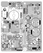
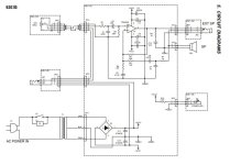
I FOUND A SCHEMATIC OF A FOSTEK 6301B Personal Monitor Self-Powered, FOR REFERENCE MAYBE SOMEONE EXPART CAN MAKE A CLONE PCB FOR DIY.
Attachments
The problem with this kit is it includes a fake chip. You can get UTC TDA2050L from profusion uk or reichelt germany which is as good as the original.
https://gb.profusion.uk/uk/tda2050l-tv
View attachment 1414203
Knew the chip would likely be fake.
That said is it fake as in is it a different chip that just so happens to work or is it a low quality clone or is it an exact duplicate?
I found this website that goes into detail about this and other similar chips.
https://electro-dan.co.uk/electronics/LM1875.aspx
https://electro-dan.co.uk/electronics/LM1875.aspx
Fakes are usually 2030 clones in 2050’s clothing. They often work fine on low voltages, but when you crank them up to +/-25 or 30 — poof!
Shipping looks like it's only $9.00 so I'll buy four of those as I intend to buy two more amps to try them bridged.
I might also order better electrolytic caps from Mouser. I'll stick with the stock values.
I'll see if 50 volt caps will fit the board.
If so I'll bump up the power supply to 35V.
I might also order better electrolytic caps from Mouser. I'll stick with the stock values.
I'll see if 50 volt caps will fit the board.
If so I'll bump up the power supply to 35V.
Last edited:
Use 1875, they go higher, up to 50V or so, circuit is same.
Price wise too not much difference.
Put a bigger heat sink.
Price wise too not much difference.
Put a bigger heat sink.
It's tempting to use that chip, however the power supply I have only goes to a max of 40V and also it's power output I really need since I am driving a 16 ohm speaker.
With the current chip which is likely a 2030 clone in a 2050 package, the amp goes loud enough. A real 2050 will be better as the amp won't have to be run as hard for the desired volume level.
To actually run the amp at its maximum .5% distortion wattage output would get me in trouble at work as the speaker would be quite loud and people would complain.
24dB is 10^(24/20) =x15.85, so (R5+R4)/R4 >~ 16. Note (22+1)/1=23 > 16. For R5=22k, 22k/14.85~=1.48k max
But you can add a resistor across + and - in so that the feedback is <= 24dB gain while the circuit gain is something less, up to the point where you hit the input common mode limit.
Perhaps R5 should be R3+(R1||R2) = 33K but this is cap coupled so offset is not an issue.
For bridging, you can slave one amp off the other. You don't need an op-amp etc. Mostly bridging half's the load impedance so this chip may not handle the current, unless you are driving 16 Ohms. 5A max into 4 Ohms is 20V, bridged or not, and the dissipation may also be a problem.
Tda2050 is better than Lm1875 if you consider low impedance loads because it can provide higher output current. For 16ohm speaker you can bridge 2*2050/1875 to get higher voltage swing. The max supply voltage of 1875 is 60VDC(higher than 2050).
Go for UTC2050, lesser distortion than LM1875
Note- JAT mistakenly called UTC2050 as fake TDA2050, its not
Note- JAT mistakenly called UTC2050 as fake TDA2050, its not
I think you should keep output caps because it ensures speaker safety. Just use good quality electrolytics.
I could, but if testing proves the bridged configuration to be desirable I might add a speaker protection circuit.
The only issue with the output coupling caps is low frequency phase shift.
To eliminate it I'd have to use just one cap and make it over 18,000uF.
Also the cap in series with R4 would need to be quite large as well.
So something like this is likely only going to be used where true HI-FI isn't needed.
- Home
- Amplifiers
- Solid State
- TDA2050 amplifier board