For the valve it's a series resistor. For the meter across it, to measure current, it's a shunt resistor. So it is context dependent.
And in push pull valve amps with fixed bias you put those resistors there to be able to easily measure the cathode current using a voltmeter, 99% of the time.For the valve it's a series resistor. For the meter across it, to measure current, it's a shunt resistor. So it is context dependent.

Yeah, it's a little strange, I made the thread 2 days ago, nobody had trouble understanding what I meant regardless, the question was answered, yet here comes captain pedantic to save the day, lol.
I dunno. Slow news day, I guess.
I dunno. Slow news day, I guess.
I think I'm going to start using slightly odd descriptions of things in the future, it seems folks are more eager to correct an error than they are to answer a question.
The last question I had, if anyone wants to chime in, was about the 0.01uf bypass capacitors, which honestly, I don't even really care about enough to keep the thread open.
I'm just gonna put some vishay 0.01uf 1000v caps in there instead and call it good.
Back to having nightmares about whether or not the ccs is going to oscillate using these little breakout boards and if I'm going to have to do something else. I bet I can solder the tab straight down to the board, I think it will fit conveniently where the drain needs to go.
Ok, so let's try and be helpful.
Personally, I don't bother with bypass caps.
I've read through the thread, but can't place your 'css question'. What were you planning to css?
Having just one negative bias adjustment for 2 valves will only work well if the 2 valves are matched. Otherwise it's good practice to break the bias up into 2 seperately adjustable voltages to ensure equal anode currents.
Hope this helps!
......but it's littered with these 0.01uf "wondercap" bypass caps,
I'd call them ''litter,'' too. They only add their value to the common parallel value. Coupling or bypass, they are redundant.
Sorry, lol I've had a couple of different threads, I lost track of what's been mentioned where.Ok, so let's try and be helpful.
Personally, I don't bother with bypass caps.
I've read through the thread, but can't place your 'css question'. What were you planning to css?
Having just one negative bias adjustment for 2 valves will only work well if the 2 valves are matched. Otherwise it's good practice to break the bias up into 2 seperately adjustable voltages to ensure equal anode currents.
Hope this helps!
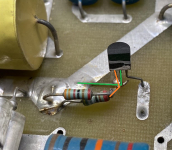
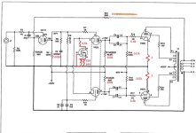
Basically, I'm working on this old arc vt60. When they first released the amp, the driver pair was biased using resistors, as you'd expect. About 2 years later, arc released a "sonic improvement" kit, that I guess you could order and modify the amp yourself. I've marked on the schematic what parts have changed, and although arc never comes out and says it (they color over the fets so you can't read the number) I was able to scrape enough of it off to figure out it's a 2535 mosfet.
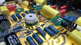
The issue is, the instructions had the person solder it dead bug style, and it's just kinda ugly and gross, so I've been trying to figure out a better way to do it. I got a few extra 2535 mosfets in both to-92 and to-220 packages, just to experiment with various ways of mounting and wiring. Right now, it's on a small board that was meant to be a 2512 size breakout board along with the set resistors, arc wanted 2 499r in parallel.
It hasn't been powered up yet because I'm still fussing with fixing solder and making a few changes, but over the last couple of days, since I've been reading more and more about ccs implementation, I'm becoming increasingly paranoid that the increase in lead lengths and using the boards like I have are going to make it behave poorly or oscillate, so I've been trying to come up with alternate ideas. One idea which I half jokingly thought to myself...I bet there's enough room on the board to solder the fet right down, the 220 package 2535 has the drain on the case, and the spot on the board where it goes...well, it just might fit.
The pictures are how it was done by whomever modded it originally in the 90s with arc's instructions, and the second one shows the board I was going to use that I'm having second thoughts about. Ignore the blue circles on the schema, I'm still messing with it, I'll probably make a final one with kicad later.
Edit: Attached a version of the schema that has more corrections on it.
Attachments
Last edited:
I should mention, I also snuck a ferrite bead onto the drain leg under the board. Figured it couldn't hurt.
FETs, like all semi-cons, are made to very wide tolerances. The amp manufacturer will have sorted incoming devices into Idss groups and painted the groups with color codes. Each group will need different associated resistors to output the desired current, or maybe will be saved for different applications. In this case, it's not a plot.
All good fortune,
Chris
All good fortune,
Chris
I had considered this, but in all the reading I've done about css in the last couple of days, it doesn't seem to be a point that gets much mention. Everyone seems to be pretty confident mentioning a device part number and a resistor for a particular current.Each group will need different associated resistors to output the desired current
Perhaps modern part tolerances are close enough.
I suppose I can test them and see how much current actually goes through them. I think it should be ~8mA for 6922s.
FET manufacturers don't just throw away every device that doesn't fall within 5% or some number of bogey. They batch test them into Idss groups of about 2:1 or 3:1 and sell them spec'd to be within that batch. If the device is required to be tighter tolerance than that, which is the case for CCS use, the buyer needs to sort from there. If you don't want to sort yourself, you can trim what you have with the resistor value.
All good fortune,
Chris
All good fortune,
Chris
I still have 2 spares, I can test them later and see what I've got, but all I have is one of those cheap component testers.
Hopefully I don't have to order 20 more and start sorting.
Hopefully I don't have to order 20 more and start sorting.
In about 2 minutes I'm just gonna order a couple of pmillet's cascode boards and be done with 'er. lol
Well, according to this little tc1 tester, the two spare to-220 dn2535 fets measure nearly identically, only Vg is different, one reads 2.17, the other 2.16.
Maybe I got lucky and this batch is pretty close, or my little tester is telling fibs, which is possible.
Edit: Also, 2 of the 4 to-92 package ones I got are identical, and the other 2 are within .2 mA for Id.
Maybe I got lucky and this batch is pretty close, or my little tester is telling fibs, which is possible.
Edit: Also, 2 of the 4 to-92 package ones I got are identical, and the other 2 are within .2 mA for Id.
FETs that come from nearby, on the same die, are usually very closely matched. All you need to choose for CCS duty is an associated source bias resistor, which can be done with a 9 VDC battery, a pot, maybe 2K ohms or so (to substitute for the source resistor), a small resistor of about 100R in series with the drain (to measure current across) and a DVM.
8mA is way too high a guess. Consider the valves' anode resistors and the voltage drop across them. 330V - 178V = 152 VDC / 100K Ohms, x2 = 3.04mA. 8mA would probably be a better number, but anode loads would need to be adjusted.
All good fortune,
Chris
8mA is way too high a guess. Consider the valves' anode resistors and the voltage drop across them. 330V - 178V = 152 VDC / 100K Ohms, x2 = 3.04mA. 8mA would probably be a better number, but anode loads would need to be adjusted.
All good fortune,
Chris
I'm not sure why I had 8mA in my head, I think I must have read something in a thread talking about 6922 max, or maybe it was 7308, I can't remember.8mA is way too high a guess. Consider the valves' anode resistors and the voltage drop across them. 330V - 178V = 152 VDC / 100K Ohms, x2 = 3.04mA.
But yeah, in general I'm 110% in favor of running tubes cool, I think I have the kt88s in my vtl amps running at about 25mA each lol
I have a couple of little boards I had made up when I first started thinking about doing this that will support this circuit, right now I have a 200r trimmer in series with 200r on the source and a 100r on the drain. I'll fire it up tomorrow and see what I can get.a pot, maybe 2K ohms or so (to substitute for the source resistor), a small resistor of about 100R in series with the drain (to measure current across) and a DVM.
Thanks for the tips and help!
That is exactly what a shunt resistor is there for, to measure the current.and you can’t use a shunt resistor to measure current.
- Home
- Amplifiers
- Tubes / Valves
- ARC VT60 - Asking lots of questions